
Standard solution: AFLS cabinet — automatic frequency load shedding 35/10 kV
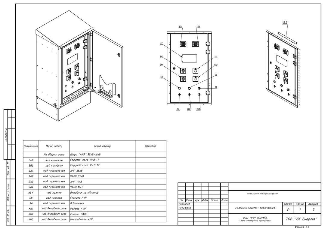
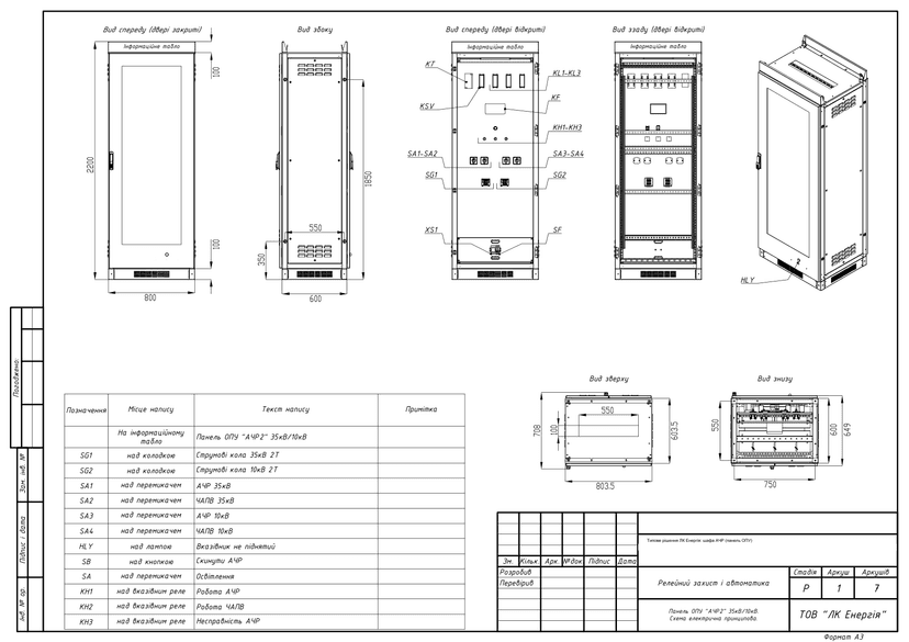
Standard solution for a 35/10 kV AFLS cabinet based on the RZM-A.ACHR device: a separate cabinet and an OPU (general substation control point) panel, FAAR circuits and signaling. PDF diagrams are open access, DWG set after registration.
Solution files
2 PDF · 1.5 MB — open access- "AFLS" 35kV/10kV cabinet — schematic electrical diagram (7 sheets, 2025)PDF · 777 KBdiagram7 sh.
- OPU "AFLS2" 35kV/10kV panel — schematic electrical diagram (7 sheets, 2026)PDF · 791 KBdiagram7 sh.
DWG set — after a short registration (name, phone, e-mail). The download link appears on screen right after registration and is valid for 7 days.
Get DWGPublished: 11.06.2026 · Author: engineering department of LK Energy Group
A ready-made set of diagrams for the standard solution of an AFLS cabinet — automatic frequency load shedding for 35/10 kV substations, in two versions: a separate "AFLS" 35kV/10kV cabinet and an OPU "AFLS2" 35kV/10kV panel (OPU = general substation control point) — two PDF files, 7 sheets each, with schematic electrical diagrams, terminal strip layouts and equipment lists. The solution is built around the specialized RZM-A.ACHR AFLS device and is based on real substation reconstruction projects (2025–2026). The diagrams are freely available below; the DWG set is provided free of charge after a short registration.
What is AFLS, and when does the system operator require an AFLS cabinet
Automatic frequency load shedding (AFLS) is an emergency automation function of the power system. During an emergency active-power deficit, the grid frequency drops, and the AFLS device automatically disconnects predetermined loads to stop the frequency decline. Once the frequency recovers, FAAR (frequency automatic autoreclosing) returns the disconnected load to operation. An AFLS cabinet is a structurally complete protection-and-automation (RZA) assembly that brings together in one place the AFLS device, measuring-voltage and current-blocking circuits, AFLS and FAAR enable/disable switches on the 35 kV and 10 kV sides, and output circuits for incomer tripping and signaling.
The diagrams are based on real substation reconstruction projects: the RZA section of such projects often calls for a separate AFLS cabinet or panel.
Technical parameters of the solution
- Two versions: a separate "AFLS" 35kV/10kV cabinet (with heating, lighting and socket circuits) and an OPU "AFLS2" 35kV/10kV panel measuring 2200×800×600 mm for installation in the OPU
- AFLS device: RZM-A.ACHR with AFLS1, AFLS2 and FAAR output relays
- Two measuring voltages to the device: from the 35 kV voltage transformer (~100 V) and/or from the 10 kV station service transformer via an OSM-0.25 220/100 V transformer; measuring-voltage monitoring relay
- Current circuits on the 35 kV and 10 kV sides — via UTWE 6/4+1 test blocks (device current blocking)
- DC control circuits =220 V; AFLS 35 kV / FAAR 35 kV / AFLS 10 kV / FAAR 10 kV enable/disable switches, an "AFLS Reset" button
- Output circuits: 35 kV and 10 kV incomer tripping, autoreclosing blocking, fault recorder, central signaling
- Relay wiring: VL-100A time relays, PE-40 auxiliary relays, REU11-21 flag relays; "AFLS operation", "FAAR operation", "AFLS fault" signals
- Terminal section: URTK 6 measuring terminals with test sockets, AVK feed-through terminals
- Years of development: 2025–2026, diagram language: Ukrainian
- Site-specific AFLS/FAAR settings are not included in the set — they are determined by the site-adaptation design project
Set contents and downloads
| No. | Document | Contents | File |
|---|---|---|---|
| 1 | "AFLS" 35kV/10kV cabinet — schematic electrical diagram (7 sheets, 2025) | RZM-A.ACHR device and FAAR circuits, measuring voltage from the 10 kV station service transformer and the 35 kV voltage transformer, terminal strip layouts, equipment list | |
| 2 | OPU "AFLS2" 35kV/10kV panel — schematic electrical diagram (7 sheets, 2026) | Overall views 2200×800×600 mm, AFLS/FAAR circuits from two 35 kV voltage transformers, terminal strip layouts, equipment list |
Preview
DWG set after registration
You get the complete DWG models of both versions (schematic electrical diagram, overall views, terminal strip layouts and equipment lists in a single AutoCAD file) free of charge after registration. Registration takes your name, phone and e-mail.
Frequently asked questions
Can this solution be used in my own project?
Yes — as a standard baseline solution for the RZA section. Site adaptation, AFLS/FAAR settings and load-shedding stages are determined by the designer in the design project for the specific substation. The diagrams are based on real substation reconstruction projects (2025–2026).
What equipment is included?
The RZM-A.ACHR AFLS device, VL-100A time relays, PE-40 auxiliary relays, REU11-21 flag relays, UTWE 6/4+1 test blocks, 4G16 switches, URTK 6 measuring terminals. In the cabinet version — an OSM-0.25 220/100 V transformer to supply measuring voltage from the station service transformer.
What is the difference between the AFLS cabinet and the OPU "AFLS2" panel?
The circuit design is identical. The separate cabinet is a self-contained enclosure with heating, lighting and a socket; the OPU panel, measuring 2200×800×600 mm, is installed in the general substation control point and has only lighting and a socket.
Does AFLS have to be built as a separate cabinet?
No. AFLS can also be implemented as a function of the switchgear bay RZA terminals — see the standard KRUN switchgear solution. A separate AFLS cabinet or panel is used when the project singles out automatic frequency load shedding as a standalone unit at the substation.
Does LK Energy Group manufacture AFLS cabinets?
Yes. We manufacture AFLS cabinets and other RZA equipment at our own production facility in Odesa; see also the equipment catalog.
How can I get the DWG files and a consultation?
Click "Get DWG" in the "Solution files" block at the top of the page and complete a short registration (name, phone and e-mail). How you will receive the set is shown in the same block. We advise designers on RZA equipment composition: +38 067 104 94 91.
Delivered project: UFLS and line protection cabinets for two 35/10 kV substations
The diagrams are provided as a reference standard solution. Site adaptation, RZA settings calculation and compliance with applicable norms (PUE, DSTU (Ukrainian national standards), DBN (Ukrainian building codes)) are the responsibility of the designer. LK Energy Group is not liable for the use of this solution without adaptation to the conditions of a specific site.
Any questions left?
Write or call us — we answer to the point. Preliminary reply within 24 hours.
+380 67 104 94 91