
UKM: reactive power compensation — when you need it and how to choose
Author: Volodymyr Ledok, Production Technical Director at LK Energy Group.
He runs the manufacture of switchboard equipment in Odesa — from approving the diagram to acceptance testing of the finished enclosures. Every reactive power compensation unit goes through a test-bench check before shipment: controller operation, stage switching, measuring circuits.
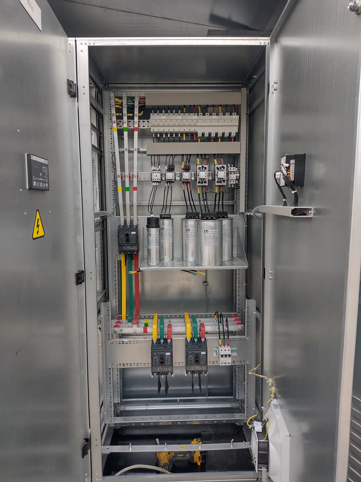
A UKM (reactive power compensation unit) is an enclosure with capacitor banks that produces reactive power directly on site, so that the plant does not draw it from the external network. The same equipment goes by different names in documentation: UKM, UKRM, KRM, capacitor unit — they all mean the same thing. There is one goal: raise cos φ to the value required by the contract with the distribution system operator, reduce the charge for reactive energy flows and relieve cables and transformers of unnecessary current.
What reactive power is and why it has to be compensated
Any equipment with magnetic circuits — motors, transformers, reactors — draws not only the active power P that does the useful work, but reactive power Q as well. At the consumer it is not converted into work or heat; it merely swings back and forth between the source and the load, building up magnetic fields. Together they add up to the apparent power S, and the ratio between them is described by the power factor: cos φ = P/S. The lower the cos φ, the more current flows through the network for the same useful work.
For a plant, uncompensated reactive power means three things:
- Charges for reactive energy flows
- the meters at the point of balance-sheet demarcation record reactive energy separately, and the contract with the consumer provides for a charge on those flows. This is not a penalty in the everyday sense but a separate line in the invoice — and it goes down as far as the reactive power is compensated on site.
- Loading the network with “idle” current
- the reactive component of the current heats the cables and takes up line capacity and transformer rating. At a low cos φ a transformer can be loaded to the limit in apparent power while delivering considerably less active power.
- Voltage dips
- extra current means an extra voltage drop across cables and windings. After compensation the voltage level on the busbars, as a rule, stabilises.
The cheapest source of reactive power is the capacitor: it supplies reactive power in antiphase to the inductive load. Put a capacitor bank next to the consumer and the reactive power circulates around a short “capacitor — motor” loop, without passing through the meter, the transformer and the DSO network.
When a plant needs a UKM
The typical consumers of reactive power are practically all the power equipment of a production site:
- Induction motors
- pumps, fans, compressors, conveyors, machine tools. The main source of reactive power at most plants; an underloaded motor has a particularly low cos φ.
- Welding equipment
- welding transformers and rectifiers — a low cos φ plus a rapidly fluctuating load pattern.
- Transformers
- their own magnetising reactive power draw, noticeable when they are underloaded.
- Induction furnaces, lift and crane equipment
- any inductive load adds its share.
Practical signs that a UKM is what you need: the invoice has a line for reactive energy; the actual cos φ at the incomer is below the contracted value; the technical conditions (TU) or the power supply design explicitly require compensation; the substation or the incoming cable is working at its limit while the active load stays unchanged. For new sites the compensation requirement is usually built into the grid connection design.
Types of UKM: fixed, automatic, with filter reactors
Structurally, any UKM is capacitor banks, switching devices and protection inside an enclosure. The difference lies in the control method and in the tolerance to harmonics.
A fixed (unregulated) unit keeps the capacitors permanently energised, with an output that does not change. It is justified where the load is steady: individual compensation of a particular motor or transformer. If the load varies, at night a fixed bank will overcompensate — and reactive power exported into the grid is metered and billed just the same.
An automatic UKM is the main option for a plant incomer. The reactive power controller measures current and voltage through a current transformer at the incomer, calculates the present cos φ and uses contactors to switch capacitor stages in and out, holding the set power factor under any load profile. Capacitors are switched by dedicated capacitor contactors with pre-charging resistors that limit the inrush charging current.
A UKM with filter reactors is for networks with a large share of non-linear loads: variable frequency drives, rectifiers, UPS units, welding inverters. Such loads generate harmonic currents, and a capacitor presents a low impedance to harmonics: the bank is overloaded, it heats up and — most importantly — the “capacitors — network inductance” circuit can fall into resonance at the frequency of one of the harmonics. A series filter reactor detunes the circuit below the dangerous frequencies, protects the capacitors and keeps the unit from amplifying harmonics.
Dynamic (thyristor) compensation — the stages are switched by thyristor switches within fractions of a second, with no contact wear. It is needed for rapidly fluctuating loads: welding lines, presses, cranes, hoists — wherever a contactor-based unit simply cannot keep up with the load profile.
| UKM design | How it works | For which sites |
|---|---|---|
| Fixed (unregulated) | Capacitor bank of constant rating, no controller | Steady load; individual compensation of a motor or transformer |
| Automatic | The controller holds the set cos φ by switching stages through capacitor contactors | Plant incomer with a varying load profile — the typical solution |
| Automatic with filter reactors | Each stage is a capacitor with a series reactor detuned away from the harmonics | Networks with variable frequency drives, rectifiers, UPS units, welding inverters |
| Dynamic (thyristor) | Contactless stage switching within fractions of a second | Rapidly fluctuating loads: welding, presses, cranes |
How to choose a UKM: calculating the rating in kvar
The required compensation rating is calculated with the classic formula:
Qc = P · (tg φ1 − tg φ2), where P is the active power of the load, tg φ1 corresponds to the actual cos φ, and tg φ2 to the target one set by the contract with the DSO or by the design.
There are two workable ways to obtain the input data:
- From the electricity invoices
- the active and reactive energy figures for several representative months give the plant's average tg φ. A quick way to make a preliminary selection.
- Measurement with a network analyser
- logging P, Q, cos φ and harmonics at the incomer over a day to a week. The more accurate route: you see the reactive power peak, how it varies over time and the harmonic level — in other words, it is immediately clear whether filter reactors are needed and what the stages should be.
Besides the total rating in kvar, four more things matter when choosing a unit. Stage breakdown: the smallest stage determines the control resolution — typical arrangements such as 2×25 + 2×50 kvar let the controller build up the output in small steps. Harmonics: if the share of non-linear load is significant, only a design with reactors will do; ordinary capacitors do not last long in such a network. Installation point: central compensation at the main switchboard incomer reduces the charge for reactive power, while individual compensation next to a large load also relieves the internal cables. Room for growth: spare space in the enclosure for additional stages costs less than a second unit two years later.
Building a UKM for a specific site
There is no ready-made unit that fits every case: the rating, the number and step of the stages, the presence of reactors, the type of controller and of the incomer all depend on the particular network. The working sequence is as follows: data from the invoices or measurements → calculating the kvar and splitting it into stages → selecting capacitors, contactors and protection → assembly and a test-bench check. We build UKM reactive power compensation units at our own plant in Odesa — from compact wall-mounted enclosures to multi-stage units with filter reactors, to a customer questionnaire or the customer's design.
Frequently asked questions
How is an automatic UKM better than a fixed one?
A fixed bank delivers a constant output regardless of the load: during the day it may not be enough, at night it overcompensates, and reactive power exported into the grid is metered and billed as well. An automatic unit uses its controller to match the number of connected stages to the actual load profile and holds cos φ within the set limits around the clock. For a plant incomer with a varying load this is the standard solution.
When is a UKM with reactors needed?
When the network has a noticeable share of non-linear loads — variable frequency drives, rectifiers, UPS units, welding inverters. They generate harmonics that overload the capacitors and can drive the “bank — network” circuit into resonance. A filter reactor in series with the capacitor detunes the circuit away from the dangerous frequencies. Whether reactors are needed in your particular case is answered by measuring harmonics with a network analyser at the incomer.
How do we find out how many kvar our plant needs?
Either from the electricity invoices (active and reactive energy for representative months give the actual tg φ, followed by the calculation Qc = P·(tg φ1 − tg φ2)), or, more accurately, from a day-long measurement with a network analyser. The second route is better: it shows the reactive power profile, the stage step required and the harmonic level straight away. Send us your invoices or measurement results and we will put together a configuration.
LK Energy Group builds reactive power compensation units at its own plant in Odesa: automatic UKM units, versions with filter reactors, custom configurations to a questionnaire. Every enclosure goes through a test-bench check of the controller and of the stage switching before shipment. Standard solutions are on the UKM page; to have one selected for your site, get in touch with us.
See also
Need an engineer’s advice?
Have a task involving power supply, switchgear or solar plants — write to us and we’ll answer to the point.
+380 67 104 94 91