
Typical Solution: UKM — 0.4 kV Reactive Power Compensation Unit
Typical schematic diagrams of UKM — 0.4 kV reactive power compensation units at 40, 110 and 320 kVAr, and as part of the ShchO 90 switchboard. PDF is open access, DWG after registration.
Solution files
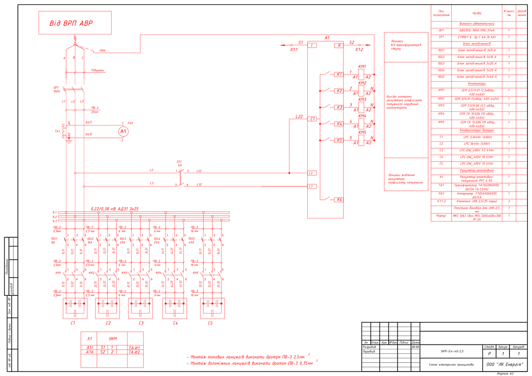
5 PDF · 641 KB — open access- UKM-0.4-40-2.5 — diagram + bill of materialsPDF · 109 KBdiagram
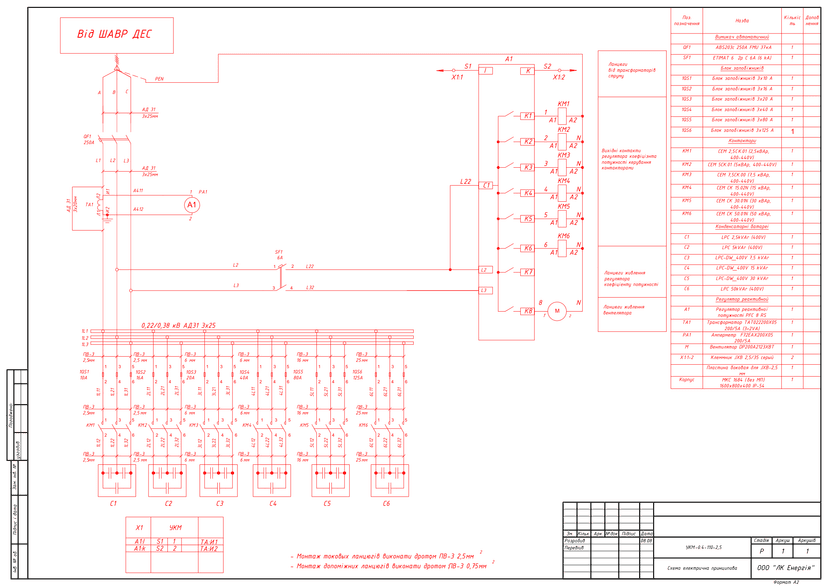
- UKM-0.4-110-2.5 — diagram + bill of materialsPDF · 112 KBdiagram
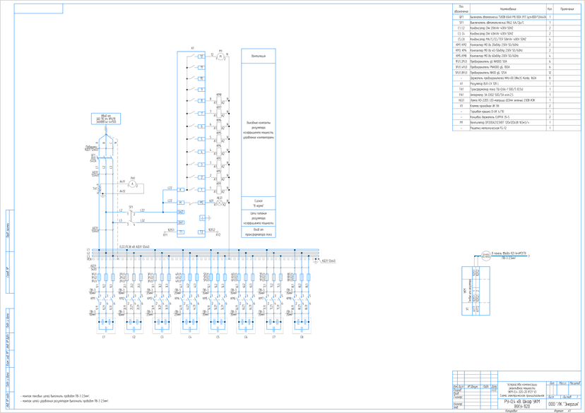
- UKM-0.4-320-20 IP21 U3 — diagram + bill of materialsPDF · 135 KBdiagram
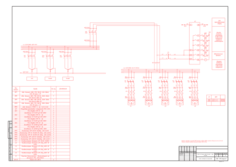
- ShchO 90-1400 panel with UKM — diagram + bill of materialsPDF · 118 KBdiagram
- UKMF-0.4-480-10 — filter-type UKM with reactorsPDF · 168 KBdiagram
DWG set — after a short registration (name, phone, e-mail). The download link appears on screen right after registration and is valid for 7 days.
Get DWGPublished: 11.06.2026 · Author: engineering department of LK Energy Group
Five field-proven schematic circuit diagrams of 0.4 kV reactive power compensation units (UKM) from real LK Energy Group orders from 2021–2024: standalone cabinets at 40, 110 and 320 kVAr, a ShchO 90 panel with a built-in UKM module, and a UKMF filter-type unit at 480 kVAr with reactors for networks with nonlinear loads. Each sheet includes a complete bill of materials — capacitor banks, contactors, a power factor controller, protection devices. The PDF is freely available below; the source diagram files (DWG) are available after a short registration.
What reactive power compensation is and why UKM is needed
Most industrial consumers — electric motors, pumps, fans, welding equipment, transformers — draw reactive power from the grid in addition to active power. The reactive component performs no useful work, but it loads supply lines, transformers and switching devices, increases voltage losses and lowers the power factor cos φ. For a low cos φ, distribution system operators charge enterprises a fee for reactive electricity (under the applicable methodology).
A reactive power compensation unit (UKM) — another common name is 0.4 kV capacitor unit (KKU) — solves this problem directly on the consumer side. Capacitor banks generate reactive power on site, offloading the network. A power factor controller measures cos φ via a current transformer at the incoming line and automatically switches capacitor stages in and out via contactors, maintaining the set cos φ value under variable load. Each stage is protected by its own fuses or a circuit breaker.
UKM units are installed in the 0.4 kV switchgear of enterprises, pumping stations, boiler houses, and commercial buildings — as a standalone cabinet next to the incoming panel, or as a built-in section of a ShchO 90 switchboard (low-voltage switchgear, RUNN). The rating and number of stages are selected based on actual load measurements at the specific site.
Technical parameters of the solution
- Rated voltage: 0.4 kV (0.22/0.38 kV busbars), 50 Hz
- Rated capacities in the kit: 40 kVAr (5 stages, minimum stage 2.5 kVAr), 110 kVAr (6 stages, minimum stage 2.5 kVAr), 320 kVAr (8 stages of 20–50 kVAr), plus a version built into a ShchO 90 panel
- Power factor controllers: PFC 6 RS, PFC 8 RS, BLR-CX 12R L
- Stage switching: contactors for capacitor banks, CEM 2.5–50 kVAr / MO up to 60 kVAr
- Capacitor banks: LPC / LPC-DW 400 V (2.5–50 kVAr per stage), DW / MA-C-CE-TER 400 V
- Stage protection: fuse blocks 3×8…3×125 A, NH-00 holders / EFD disconnectors; incoming breakers ABS103c 100 A / ABS203c 250 A / TS800N 800 A
- Metering: current transformer at the incoming line (60/5…500/5 A), ammeter
- Enclosures: MKS 1263 (1200×600×300, IP54), MKS 1684 (1600×800×400, IP54), standalone IP21 U3 cabinet; forced ventilation on the 110 and 320 kVAr units
- Design stage: R (working/detail design documentation); source file formats: DWG (AutoCAD), CDW (KOMPAS)
- The specific configuration (rating, number and step size of stages, ingress protection rating, controller type) is agreed via a technical questionnaire
Kit contents and downloads
| No. | Document | Purpose | Equipment | Language | Diagram |
|---|---|---|---|---|---|
| 1 | UKM-0.4-40-2.5 — diagram + bill of materials | Standalone cabinet, 40 kVAr, 5 stages | PFC 6 RS, CEM contactors, LPC capacitors, ABS103c 100 A input | Ukrainian | |
| 2 | UKM-0.4-110-2.5 — diagram + bill of materials | Standalone cabinet, 110 kVAr, 6 stages, ventilation | PFC 8 RS, CEM contactors, LPC capacitors, ABS203c 250 A input | Ukrainian | |
| 3 | UKM-0.4-320-20 IP21 U3 — diagram + bill of materials | Standalone cabinet, 320 kVAr, 8 stages, powered from ShchO 90, "Normal" status signal, ventilation | BLR-CX 12R L, MO contactors, DW/TER capacitors, TS800N 800 A input | Russian* | |
| 4 | ShchO 90-1400 panel with UKM — diagram + bill of materials | UKM module as part of a ShchO 90 panel (RUNN), no standalone cabinet | PFC 6 RS, CEM contactors, LPC capacitors, EFD disconnectors with CH fuses | Ukrainian | |
| 5 | UKMF-0.4-480-10 — filter-type UKM with reactors | 480 kVAr cabinet with 14% reactors — for networks with nonlinear loads (protects capacitors from harmonics) | DWCAP RCT 10–50 kVAr capacitors (14%), filter reactors 10–50 kVAr, MO contactors | Ukrainian |
* Some sheets are in Russian (projects prior to 2022); new kits are produced by LK Energy Group in Ukrainian.
Diagram previews
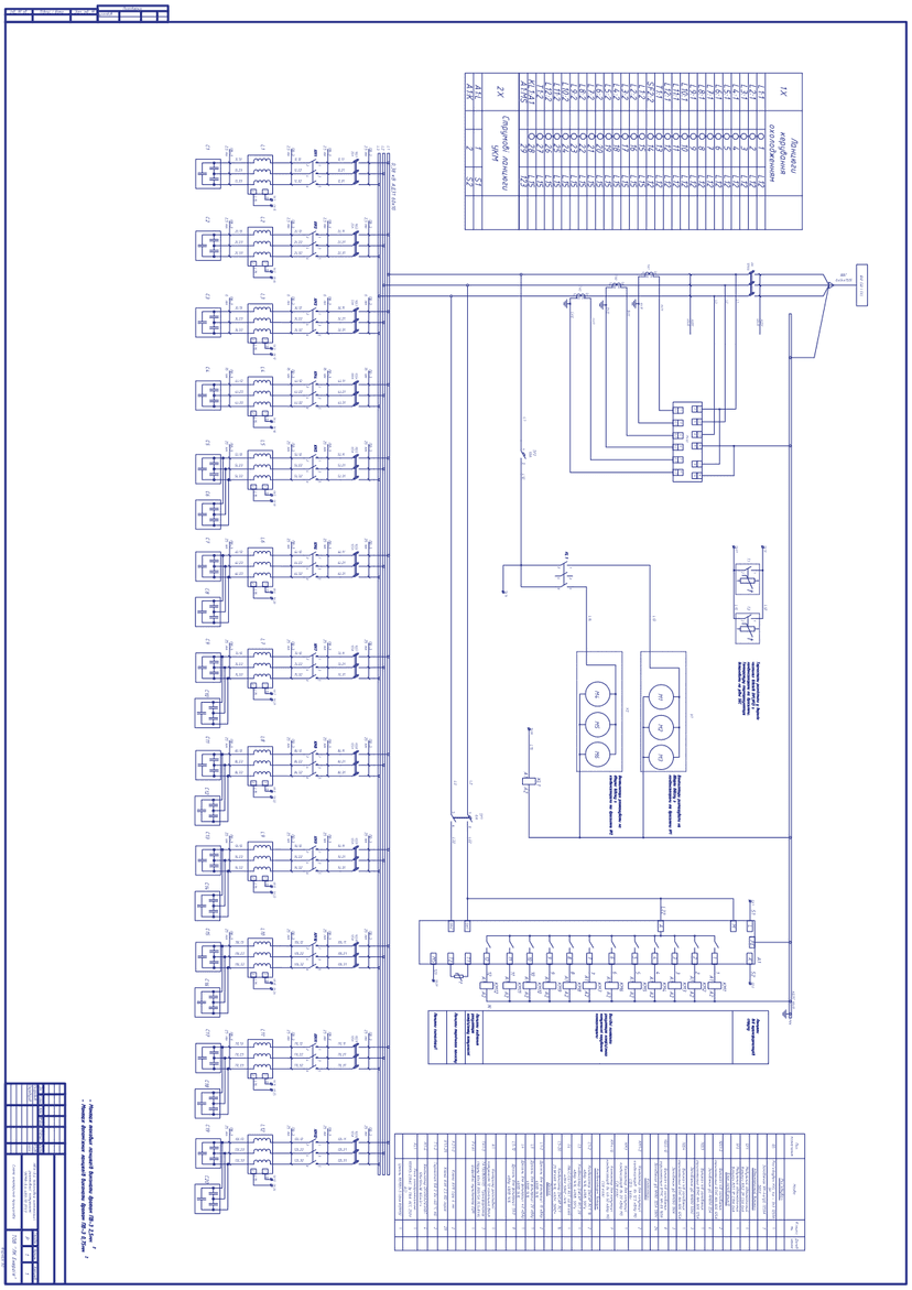
DWG after registration
Source files of the diagrams in DWG (AutoCAD) format are available free of charge after registration. Registration takes your name, phone and e-mail.
Frequently asked questions
Can these diagrams be used in a working design project?
Yes — as a baseline typical solution. Site-specific adaptation, sizing based on actual load measurements, and compliance with the applicable PUE (electrical installation rules) / DSTU (Ukrainian national standards) are the responsibility of the design engineer. The diagrams correspond to real orders manufactured by LK Energy Group in 2021–2024.
How do you select the capacity and stages of a UKM unit?
Based on measurements of the site's active and reactive power (a power quality report or measurements at the incoming line). The kit includes sizes from 40 to 480 kVAr with different stage steps; the specific rating is agreed via a technical questionnaire.
When is a UKM with reactors (UKMF) needed?
When the network has a significant nonlinear load — variable frequency drives, rectifiers, welding: higher harmonics overload standard capacitors. In a filter-type UKMF, each stage is switched in through a filter reactor (the kit includes a 14% tuning setting), which protects the capacitors and prevents the circuit from resonating with network harmonics. The kit example is the UKMF-0.4-480-10, built with capacitors rated for elevated operating voltage.
What equipment is specified in the diagrams?
Power factor controllers PFC 6 RS / PFC 8 RS / BLR-CX 12R L, CEM and MO capacitor contactors, LPC / DW 400 V capacitor banks, stage protection with NH/CH fuses. Our archive also includes versions with other equipment — contact us.
How can I get the DWG files?
Click "Get DWG" in the "Solution files" block at the top of the page and complete a short registration (name, phone and e-mail). How you will receive the set is shown in the same block.
Does LK Energy Group manufacture UKM units to these diagrams?
Yes. We manufacture UKM units as standalone cabinets and as part of ShchO 90 panels / RUNN cabinets at our own production facility in Odesa — over 3,000 units of equipment produced since 2015. We will help you select the rating and fill out the technical questionnaire: +38 067 104 94 91.
Delivered project: A 230 kVAr power-factor correction unit with 10 kVAr steps in the КТПГС-1000 package
The diagrams are provided as a reference typical solution. Site-specific adaptation, verification of protective device selectivity, and compliance with applicable standards (PUE, DSTU, DBN — state building codes) are the responsibility of the design engineer. LK Energy Group is not liable for the application of this solution without adaptation to the conditions of a specific site.
Any questions left?
Write or call us — we answer to the point. Preliminary reply within 24 hours.
+380 67 104 94 91