
Reactive power compensation units (UKM) — capacitor banks
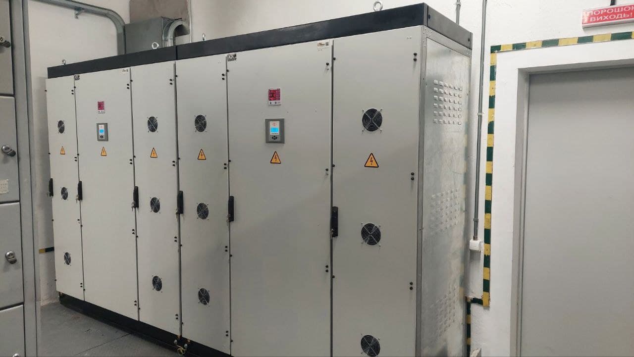
General information
UKM-0.4 is a capacitor bank that holds the target power factor, cos φ, in a 400 V, 50 Hz network. It is needed where inductive load dominates: asynchronous motors, machine tools, welding, power transformers, lighting ballasts. The unit generates reactive power on site, unloads the network and transformers, and removes the reactive energy charge or penalty.
The unit is fitted with capacitors, which form the basis of compensation. Detuning reactors (anti-resonance / filter type) are added where the load composition calls for them: when there are non-linear loads, an elevated level of higher harmonics or a resonance risk. A microprocessor-based controller automatically switches stages on and off according to the actual load, keeping cos φ close to the set value without the involvement of on-duty personnel. LK Energy Group (a switchgear equipment manufacturer, Odesa; company since 2005, own factory since 2015) manufactures UKM units to the parameters of a specific facility; the component manufacturer is chosen by the customer, subject to availability and project requirements.
Each unit is designed for the actual reactive profile of the facility: power, number and step of regulation stages, and design are determined per the project/specification. By eliminating overpayment for reactive energy, the unit reduces electricity costs; the payback period depends on the tariff, the cos φ level, and the operating mode, and is determined by calculation for the specific facility.
| Parameter | Value |
|---|---|
| Type | UKM-0.4 |
| Rated voltage | 0.4 kV (400 V) |
| Frequency | 50 Hz |
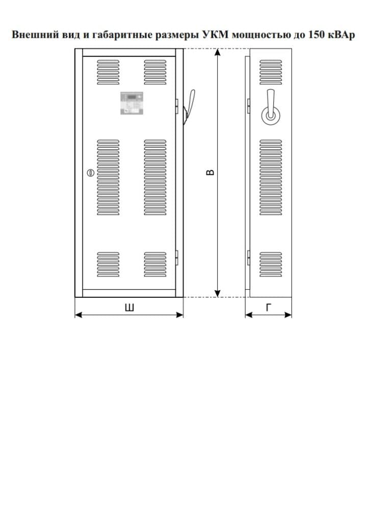
| Unit power | 25–600 kvar (exact rating — per project/specification) |
| Regulation step | per project/specification |
| Regulation | automatic, microprocessor-based controller |
| Compensation | capacitors; detuning reactors — depending on the load composition |
| Configuration | manufacturer of the customer's choice |
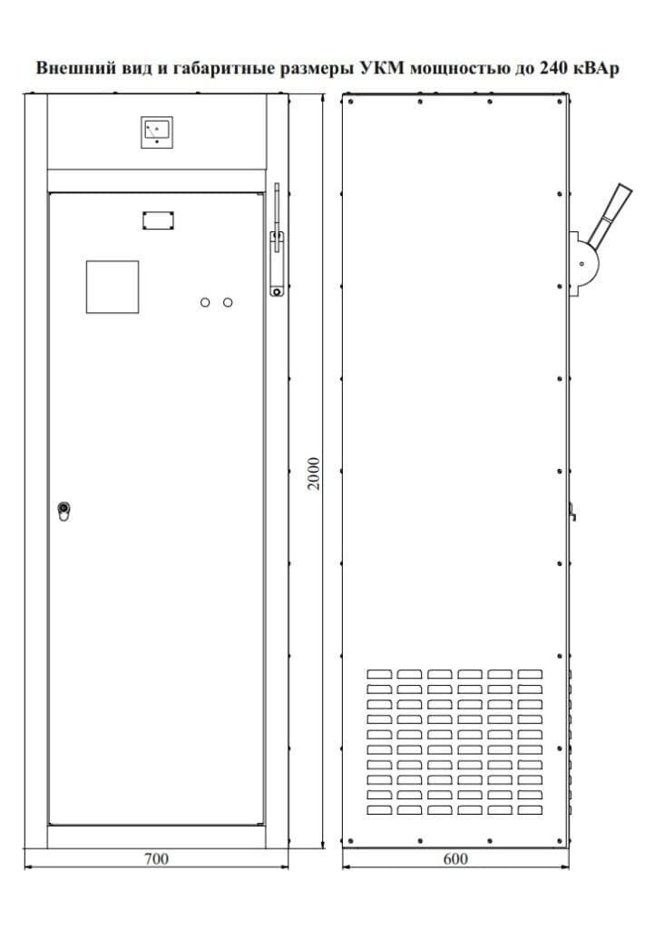
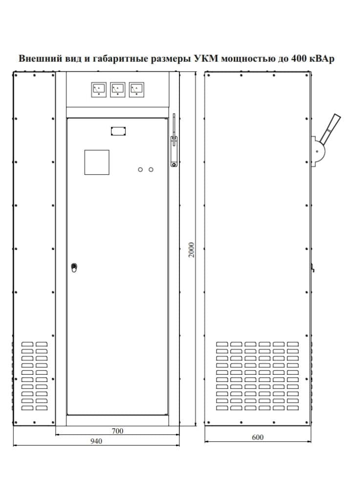
| Degree of protection, climatic design, dimensions | per project/specification |
Why a UKM needs detuning reactors
Anti-resonance (filter) detuning reactors are connected in series with the capacitor stages. They shift the resonant frequency of the circuit below the lowest significant harmonic of the network: at harmonic frequencies the circuit stays inductive, so no resonant amplification arises at those frequencies, and the capacitors are neither overloaded by harmonic currents nor overheated by them — this removes one of the main reasons why a bank’s service life is cut short. Detuning reactors are considered where non-linear loads make up a noticeable share — variable frequency drives, inverter welding machines, rectifiers, uninterruptible power supplies. For a purely inductive load without distortion, reactors are not required. We determine the need for reactors from the load composition and on-site measurements, and we build UKM units with reactors where they are needed.
Which UKM configuration your site needs
| Load type | Configuration | What to send us |
|---|---|---|
| Inductive without distortion: motors, pumps, power transformers | Capacitor banks only, automatic step control | Electricity bill showing the reactive energy volume |
| Non-linear loads (variable frequency drives, inverter welding machines, rectifiers) or resonance risk | Capacitors plus detuning reactors (anti-resonance / filter type) | Measured cos φ and load composition |
| Exact rating and step size required | Per-project calculation: designation example UKM-0.4-100-10 U3 — 100 kvar, 10 steps | Completed questionnaire |
Dimensions
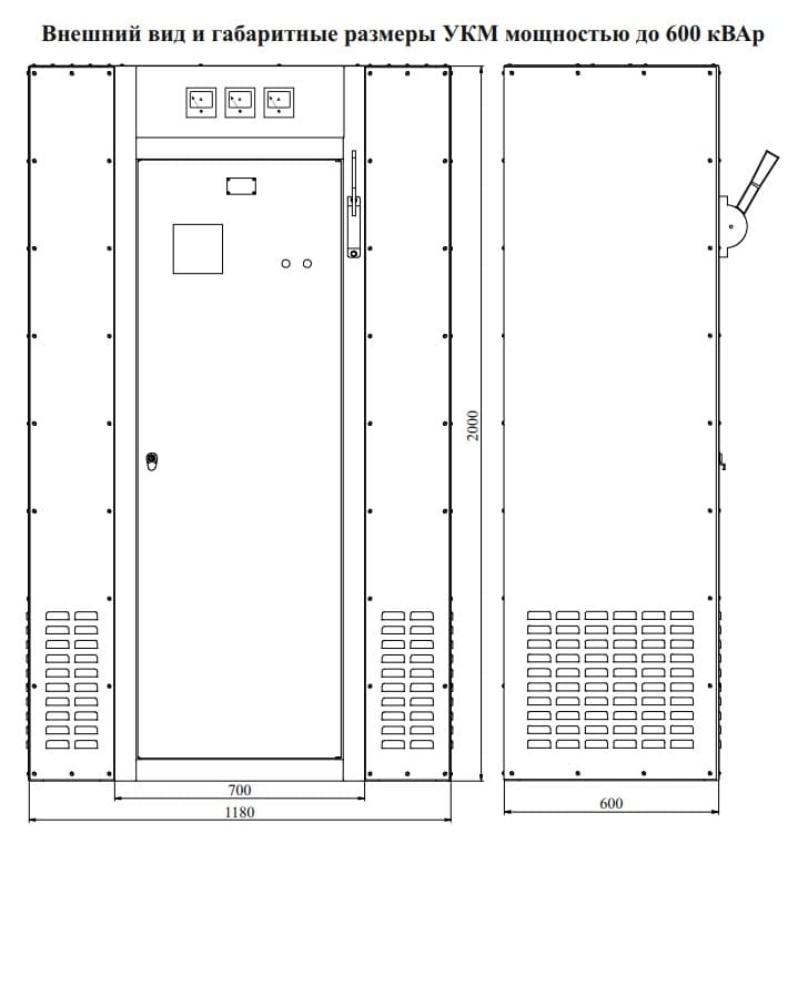
Description and purpose
UKM-0.4 is a reactive power compensation unit for 400 V, 50 Hz networks. In most cases, compensation of inductive load is performed with capacitor banks; where there are non-linear loads, higher harmonics or a resonance risk, detuning reactors are added. The regulator automatically switches steps to maintain the target cos φ without attendant staff. Range 25–600 kvar, design built to project/specification. LK Energy Group is a switchgear manufacturer from Odesa (company since 2005, own factory since 2015): we design and manufacture the unit for your load, with documentation per our own technical specifications.
The unit is connected by its own feeder to the busbars of the main distribution board (MDB) — as a separate cabinet next to the board or as a panel within it; this central compensation unloads the transformer and the incoming supply as a whole.
Technical data sheet (PDF) ↓Inquiry form for sizing →
The warranty for UKM is 2 years (extended to 5 years by agreement); enclosure metalwork — 10 years.
Find the right equipment for your site
Answer them and we will come back with a configuration and a ballpark price for your site.
FAQ
What is a reactive power compensation unit (UKM) for?
What components are used for compensation?
How quickly does the unit pay for itself?
What is cos φ and what should it be?
Is the unit a standard model or made to order?
How do I choose the right capacity of a compensation unit?
The most accurate way is your electricity bill: it shows the reactive energy consumed and the charges for it. Sizing also takes into account the measured cos φ and the load profile (motors, pumps, welding equipment). Send us your bill or a completed questionnaire — a factory engineer will size the UKM unit and its stages for your network.
How do I work out whether compensation pays off?
Will a UKM help when starting a motor?
Project example
Price request:
Reactive power compensation units (UKM) — capacitor banks
Send us your single-line diagram or specification — we will estimate the configuration, lead time and price. Preliminary estimate within 24 business hours.
+380 67 104 94 91