
Standard Solution: 10 kV RP on KSO Switchgear Cubicles — Full Set of Protection and Automation Schematics
A ready-made set of protection and automation (RZA) schematics for a 10 kV RP on KSO switchgear cubicles: 108 sheets in 10 sections — incomers, bus-tie with ATS, feeder lines, VTs, station-service transformers. PDF is open access, DWG package after registration.
Solution files
14 PDF · 14 MB — open access- Full package in a single PDF (108 sheets)PDF · 4.1 MBalbum108 sh.
- Incomer-1 (cubicle No. 9)PDF · 908 KBdiagram15 sh.
- Incomer-2 (cubicle No. 8)PDF · 908 KBdiagram15 sh.
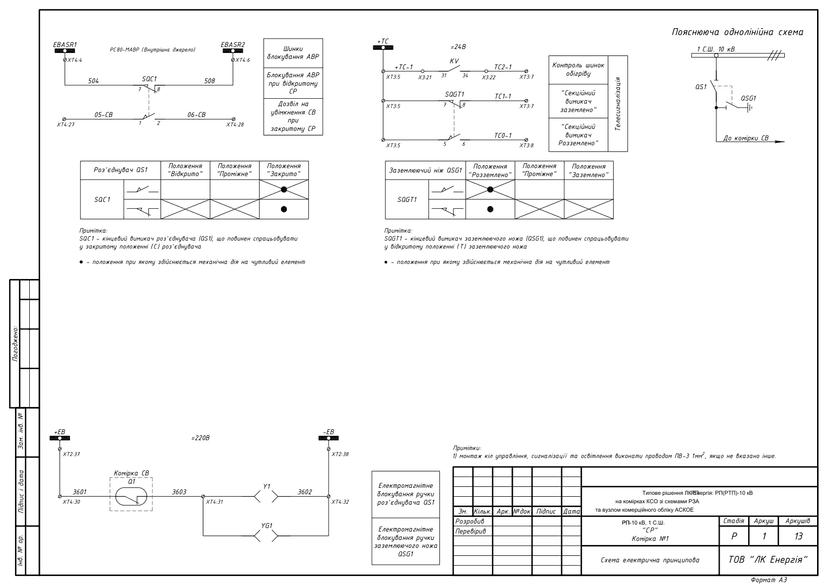
- Bus-tie circuit breaker + ATS (cubicle No. 1)PDF · 990 KBdiagram13 sh.
- Feeder cubicle, busbar section 1PDF · 885 KBdiagram13 sh.
- Feeder cubicle, busbar section 2PDF · 885 KBdiagram13 sh.
- Spare cubicle (cubicle No. 2)PDF · 890 KBdiagram15 sh.
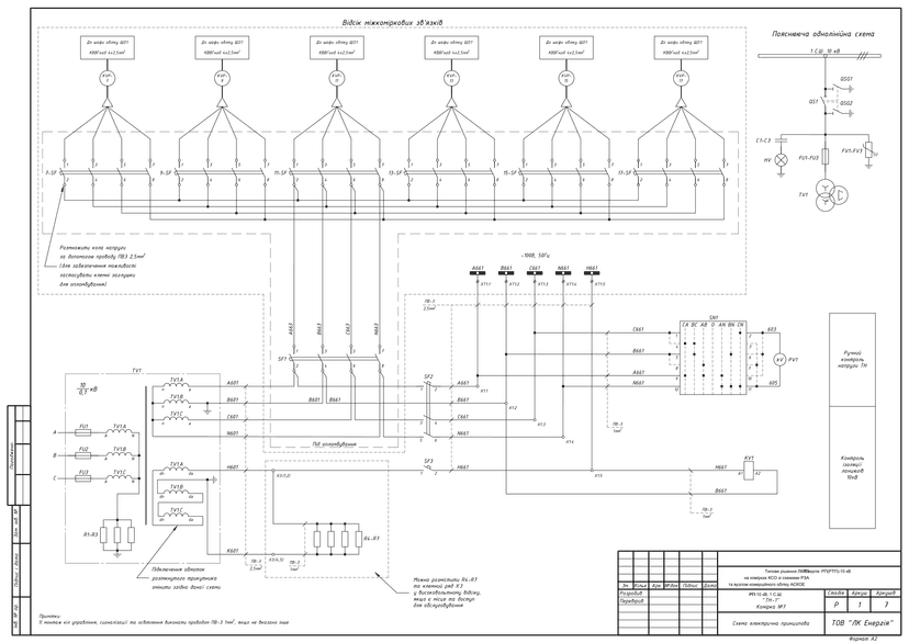
- VT-1 (cubicle No. 7)PDF · 787 KBdiagram7 sh.
- VT-2 (cubicle No. 6)PDF · 783 KBdiagram7 sh.
- Station-service transformer 1 (cubicle No. 5)PDF · 657 KBdiagram5 sh.
- Station-service transformer 2 (cubicle No. 14)PDF · 657 KBdiagram5 sh.
- Specification questionnaire — example 1PDF · 636 KBquestionnaire
- Questionnaire — example 2PDF · 635 KBquestionnaire
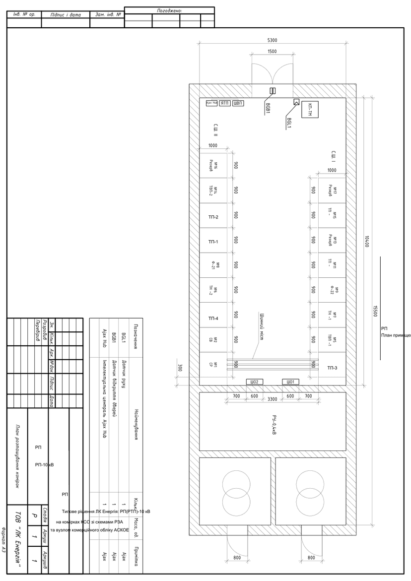
- RP premises layout plan (1:50 scale)PDF · 603 KBdrawing
DWG set — after a short registration (name, phone, e-mail). The download link appears on screen right after registration and is valid for 7 days.
Get DWGPublished: 11.06.2026 · Author: Engineering Department of LK Energy Group
A ready-made set of schematic diagrams for relay protection and automation (RZA), design stage R, for a 10 kV distribution point (RP) on KSO switchgear cubicles (single-side-access assembled cabinets) with two busbar sections: 108 sheets in 10 sections — incomers, a bus-tie circuit breaker with an automatic transfer switch (ATS) circuit, feeder cubicles, voltage transformers with metering circuits (automated commercial electricity metering system, ASKOE), and station-service transformers. The schematics were developed by LK Energy Group engineers for an actual reconstruction project of an operating 10 kV RP (2023). The PDF is freely available below; the DWG package is available after a short registration.
What a 10 kV RP is and when this solution applies
A 10 kV distribution point (RP) is an electrical installation for receiving and distributing electricity at 10 kV without transforming it. Structurally, an RP is assembled from KSO cubicles (single-side-access assembled switchgear cabinets): incomers, a bus-tie circuit breaker, outgoing feeder lines, voltage transformers, and station-service transformers. If power transformers of 10/0.4 kV are also installed in the same premises, the facility is classified as an RTP — a distribution transformer point.
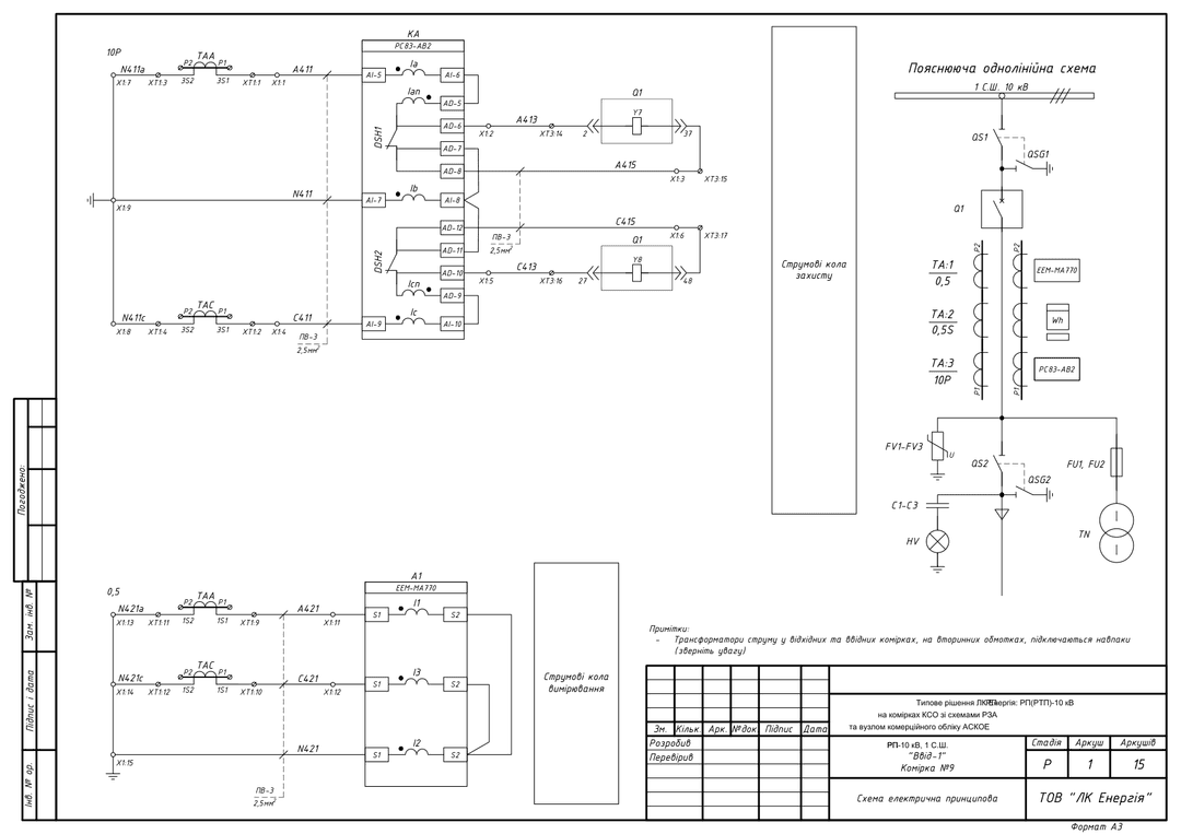
This standard solution addresses a typical task for a design engineer: a single-line diagram of a 10 kV RP with two busbar sections and a relay protection schematic for each cubicle based on RS83-AV2 microprocessor-based terminals, with metering circuits (ASKOE) and automatic transfer switching. The package was developed from an actual reconstruction project of an operating RP and can be adapted for RTPs and other configurations.
Technical parameters of the solution
- Rated voltage: 10 kV, two busbar sections
- Switching: VV-N10 vacuum circuit breakers
- Protection: RS83 series microprocessor-based terminals (RS83-AV2)
- Measurement: 3xZNOLP voltage transformers, current transformers with 0.5S / 10P windings, ASKOE commercial metering node
- Station service: TMG-25 station-service transformer
- Year of development: 2023, schematic language: Ukrainian, format: DWG (AutoCAD)
- Parameters of a specific implementation (rated currents, cubicle type, control-circuit current) are agreed upon via the specification questionnaire
Package contents and downloads
| No. | Cubicle | Purpose | Equipment | Sheets | Schematics |
|---|---|---|---|---|---|
| 1 | Incomer-1 (cubicle No. 9) | Power incomer, busbar section 1 | VV-N10, RS83-AV2, CT 0.5S/10P | 15 | |
| 2 | Incomer-2 (cubicle No. 8) | Power incomer, busbar section 2 | VV-N10, RS83-AV2, CT 0.5S/10P | 15 | |
| 3 | Bus-tie circuit breaker + ATS (cubicle No. 1) | Sectionalizing of busbar sections 1↔2, automatic transfer switching | VV-N10, RS83-AV2, ATS interlock circuit | 13 | |
| 4 | Feeder cubicle, busbar section 1 | Outgoing 10 kV lines | VV-N10, RS83-AV2 | 13 | |
| 5 | Feeder cubicle, busbar section 2 | Outgoing 10 kV lines | VV-N10, RS83-AV2 | 13 | |
| 6 | Spare cubicle (cubicle No. 2) | Spare feeder cubicle | VV-N10 | 15 | |
| 7 | VT-1 (cubicle No. 7) | Voltage measurement, busbar section 1, metering circuits (ShO1) | 3xZNOLP | 7 | |
| 8 | VT-2 (cubicle No. 6) | Voltage measurement, busbar section 2, metering circuits (ShO2) | 3xZNOLP | 7 | |
| 9 | Station-service transformer 1 (cubicle No. 5) | Station-service transformer | TMG-25 | 5 | |
| 10 | Station-service transformer 2 (cubicle No. 14) | Station-service transformer | TMG-25 | 5 |
Sections for cubicles with circuit breakers contain schematic diagrams of protection and measurement circuits, control and signaling circuits, compartment lighting circuits, and an explanatory single-line diagram.
- Full package in a single PDF (108 sheets)
- Specification questionnaire — example 1 · example 2
- RP premises layout plan (1:50 scale)
Schematic previews
DWG package after registration
You get the full package of DWG files (schematics for all cubicles, layout plan, inter-cubicle connections, ShO1/ShO2 metering cabinets, ShVP cabinet, TM cabinet, specification questionnaire) free of charge after registration. Registration takes your name, phone and e-mail.
Frequently asked questions
Can these schematics be used in a working design project?
Yes — as a standard base solution. Site-specific adaptation, relay protection setpoint calculations, the cable schedule, and compliance with the current PUE (electrical installation rules) / DSTU (Ukrainian national standards) are the responsibility of the design engineer. The schematics correspond to an actual 10 kV RP reconstruction project completed in 2023.
What equipment is specified in the schematics?
VV-N10 vacuum circuit breakers, RS83 series (RS83-AV2) microprocessor-based protection terminals, ZNOLP voltage transformers, and a TMG-25 station-service transformer. Our archive also includes versions with other equipment (VV/TEL, RS83-AV3, REF611) — contact us.
How do I get the DWG files?
Click "Get DWG" in the "Solution files" block at the top of the page and complete a short registration (name, phone and e-mail). How you will receive the set is shown in the same block.
Does LK Energy Group manufacture cubicles based on these schematics?
Yes. We manufacture KSO/KRU cubicles, low-voltage switchgear cabinets, and ShchO-90 panels at our own production facility in Odesa — over 3,000 units of equipment manufactured since 2015.
Can you help adapt the solution for my facility?
Yes, we advise design engineers on equipment selection, non-standard implementations, and filling out the specification questionnaire: +38 067 104 94 91.
Delivered project: 10 kV switching station on КСО-Е cells: 17 cubicles in Uman
Delivered project: A compact four-cell 10 kV switching station (Chornomorsk)
The schematics are provided as a reference standard solution. Site-specific adaptation, relay protection setpoint calculations, and compliance with current standards (PUE, DSTU, DBN — state building codes) are the responsibility of the design engineer. LK Energy Group bears no responsibility for applying the solution without adapting it to the conditions of a specific facility.
Any questions left?
Write or call us — we answer to the point. Preliminary reply within 24 hours.
+380 67 104 94 91