
Standard solution: 0.4 kV ATS cabinet — DEP/DGU backup
Ready-made 0.4 kV ATS cabinet diagrams with DEP/DGU backup and connection cabinets for two DEPs, 250–630 A. Free PDF, DWG set after registration.
Solution files
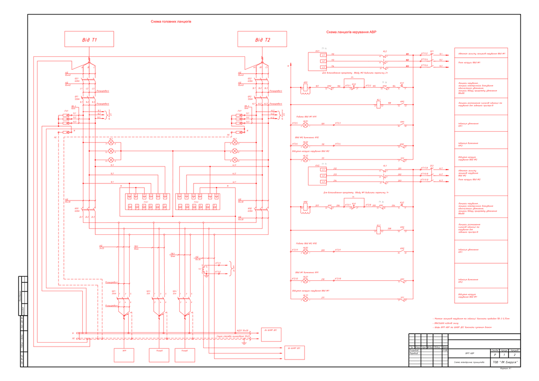
4 PDF · 855 KB — open access- ATS IDS: two network incomers (sheet 1 of 2 of the original set)PDF · 128 KBdiagram1 sh.
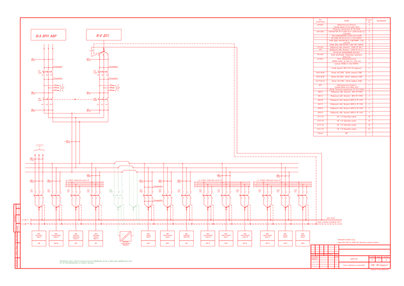
- ATS cabinet: network + DEPPDF · 379 KBdiagram3 sh.
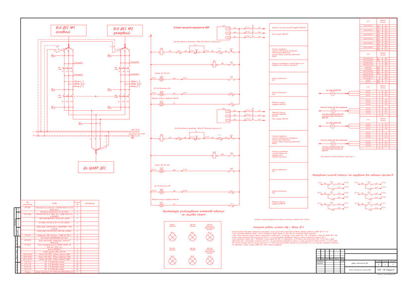
- DEP connection cabinet, 630 APDF · 142 KBdiagram1 sh.
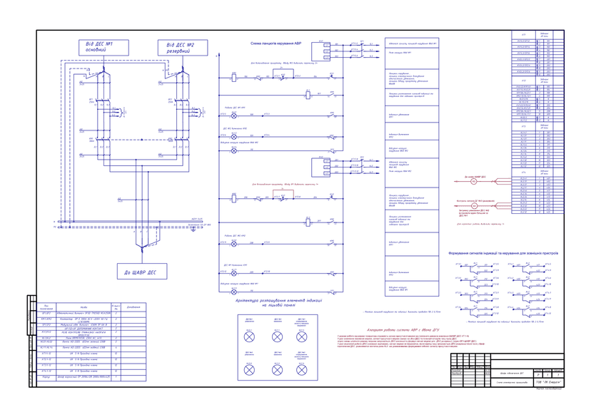
- DEP connection cabinet, 250 APDF · 206 KBdiagram1 sh.
DWG set — after a short registration (name, phone, e-mail). The download link appears on screen right after registration and is valid for 7 days.
Get DWGPublished: 11.06.2026 · Author: engineering department of LK Energy Group
A ready-made set of 0.4 kV ATS schematic diagrams, design stage P: 6 sheets in 4 versions — ATS for two network incomers (ATS incoming-distribution switchgear), an ATS cabinet with backup from a DEP (ATS cabinet), and connection cabinets for two DEPs at 250 and 630 A with control and interlock diagrams and bills of materials. The diagrams were developed by LK Energy Group engineers based on real orders from 2022-2023. PDF is freely available below; DWG is available after a short registration.
What ATS is and what types of diagrams exist
Automatic transfer switching (ATS) is a scheme that, when voltage on the main incomer disappears or deviates beyond an acceptable range, automatically switches the load to a backup power source. Structurally, the solution is implemented either as a separate ATS cabinet or as a section of a 0.4 kV incoming-distribution switchgear (IDS). Voltage on each incomer is monitored by three-phase voltage relays, and switching is performed by contactors with mechanical and electrical interlocking against simultaneous closing.
Typical configurations of a 0.4 kV ATS diagram:
- two independent network incomers
- (two transformers or two lines) — mutual backup; a separate standard solution: 0.4 kV ATS for two incomers;
- network incomer + backup from DEP/DGU
- when the network disappears, the load is transferred to the generator, and back once the network is restored;
- two generator incomers
- (main and backup DGU) — a DEP connection cabinet for facilities where generators operate in rotation.
This set covers all three configurations: a 0.4 kV ATS diagram for two network incomers, an ATS cabinet with DEP backup, and connection cabinets for two DEPs at 250 and 630 A. Incomer priority is set by a jumper, and return to the main power supply is automatic, with a time delay.
Technical parameters of the solution
- Rated voltage: 0.4 kV (380/220 V), 50 Hz
- Switching: LC1E300M5 (300 A) / LC1E630M7 (630 A) contactors with LAEM8 mechanical interlock and electrical interlock against simultaneous closing
- Incomer protection: NSX250N TM250D (250 A), TS630N 65 kA (630 A) circuit breakers
- Voltage monitoring: RM35TF30 three-phase voltage relay on each incomer
- Incomer priority: set by a jumper, without rewiring the circuit
- Time delays: auxiliary contact blocks with a 1-30 s delay; setpoints of 3-7 s per the diagrams
- Indication per incomer: on / off / no control voltage; the 250 A version has a separate indication panel
- Enclosure of DEP connection cabinets: frame cabinet 2000×1000×425 mm (per the bill of materials)
- Years of development: 2022-2023, design stage P, diagram language — Ukrainian, originals — DWG (AutoCAD)
- Rated current of the version, equipment base, ingress protection rating, climatic design — per the inquiry sheet
Set contents and downloads
| No. | Version | Purpose | Sheets | Diagrams |
|---|---|---|---|---|
| 1 | ATS IDS: two network incomers (sheet 1 of 2 of the original set) | 0.4 kV ATS between incomers from T1 and T2 — main circuits, control circuits, outgoing feeder to the UKM (capacitor bank unit) | 1 | |
| 2 | ATS cabinet: network + DEP | Main incomer from the IDS, backup from the DEP; distribution section for 12 groups; control circuits; inter-cabinet links for DGU operational interlocking | 3 | |
| 3 | DEP connection cabinet, 630 A | ATS between DEP No. 1 (main) and DEP No. 2 (backup), with a bill of materials | 1 | |
| 4 | DEP connection cabinet, 250 A | ATS between two DEPs, indication panel, operating algorithm of the ATS system with two DGUs | 1 |
The sheets contain diagrams of the main circuits, control and indication circuits, electrical and mechanical interlock diagrams, and bills of materials (where provided in the original).
Diagram previews
DWG after registration
You get the original diagrams in DWG (AutoCAD) format free of charge after registration. Registration takes your name, phone and e-mail.
Frequently asked questions
Can these diagrams be used in a working design project?
Yes — as a standard base solution. Adapting it to a specific facility, calculating currents, verifying protection selectivity, and ensuring compliance with the current PUE (electrical installation rules) / DSTU (Ukrainian national standards) is the responsibility of the design engineer. The diagrams correspond to real orders manufactured in 2022-2023.
Is this an ATS based on contactors or on motorized circuit breakers?
All diagrams in this set are contactor-based ATS (LC1E300/LC1E630) with LAEM8 mechanical interlocking and electrical interlocking against simultaneous closing in the control circuits. Please check with our engineering department regarding other versions.
How does the diagram select the priority incomer, and how does switching to the DEP work?
The voltage of each incomer is monitored by an RM35TF30 three-phase voltage relay. Incomer priority is set by a jumper on the terminal block. In the version with two DGUs, the generators receive a network-presence signal from the ATS cabinet, and the backup DEP's switch-in delay is set to twice that of the main one — the operating algorithm is described directly on the diagram sheet.
How can I get the DWG files?
Click "Get DWG" in the "Solution files" block at the top of the page and complete a short registration (name, phone and e-mail). How you will receive the set is shown in the same block.
Does LK Energy Group manufacture ATS cabinets based on these diagrams?
Yes. We manufacture ATS cabinets, IDS units, and 0.4 kV panels at our own production facility in Odesa — over 3,000 units of equipment produced since 2015. We will help you select the equipment and fill out the inquiry sheet: +38 067 104 94 91.
Delivered project: 400 A ATS panel: automatic mains-to-generator transfer
The diagrams are provided as a reference standard solution. Adapting the solution to the facility, verifying the selectivity of protection devices, and ensuring compliance with current norms (PUE, DSTU, DBN (state building codes)) is the responsibility of the design engineer. LK Energy Group is not liable for the use of the solution without adaptation to the conditions of a specific facility.
Any questions left?
Write or call us — we answer to the point. Preliminary reply within 24 hours.
+380 67 104 94 91