
Standard solution: 0.4 kV ATS for two incoming feeders (power + control circuits)
Standard solution for a classic mains 0.4 kV two-incomer ATS: power circuits and time-delayed control circuits, mutual interlock, frame sizes up to 630 A. DWG set after registration.
Solution files
There are no open PDFs for this solution — the DWG drawing set is provided after registration.
DWG set — after a short registration (name, phone, e-mail). The download link appears on screen right after registration and is valid for 7 days.
Get DWGPublished: 18.07.2026 · Author: engineering department, LK Energy Group
A ready standard solution for a classic mains 0.4 kV ATS with two incoming feeders — automatic transfer of the load from the main incomer to the standby one on loss of voltage. The set contains the power circuits and the time-delayed control circuits, mutual interlocking of the incomers and voltage monitoring. The solution is compiled from real projects of 2021–2025 (АВР-100-80 and АВР-270-630 frame sizes — up to 630 A). The DWG set is free after a short registration.
Classic mains ATS: main and standby incomers
The ATS concept is simple: the facility is supplied from one (main) incomer, and on loss of voltage the automation transfers the load, with a time delay, to the second (standby) incomer and returns the load to the main incomer once voltage is restored (automatically or manually, depending on the version). Mutual interlocking prevents both incomers from feeding the busbar simultaneously. This solution describes exactly this mains scenario of two independent grid incomers. If the standby source is a diesel power plant rather than a second incomer, see the separate standard ATS panel solution with diesel standby.
Technical parameters
- Two independent 0.4 kV incomers; automatic transfer to the standby incomer on loss of voltage on the main one
- Power circuits based on circuit breakers / switch disconnectors; frame sizes from real projects — from АВР-100-80 to АВР-270-630 (up to 630 A)
- Control circuits with time delays for transfer and return (two versions — with time relays and simplified)
- Mutual interlocking of the incomers (electrical; mechanical depending on the version), no parallel operation
- Voltage presence monitoring on both incomers
- Enclosure version IP31 / IP54 (per project)
- Drawing language — Ukrainian; based on real projects of 2021–2025
- The rated current and components are selected for the load of the specific facility
DWG set after registration
You get the full set (schematic circuit diagram of the power and control circuits, panel layout, terminal rows and equipment list) in DWG format free of charge after registration. Registration takes your name, phone and e-mail.
We manufacture the equipment at our own facility in Odesa; see also the equipment catalog.
FAQ
How does this differ from the ATS panel with diesel standby?
Here both sources are grid incomers (main and standby). In the diesel-standby ATS panel solution the standby source is a diesel power plant, and generator start/stop circuits are added. The control circuit design is similar; the power and starting circuits differ.
What is the maximum rated current?
Based on the donor projects — up to 630 A (АВР-270-630 frame size). The rating is selected for the load of the specific facility; smaller versions are also possible (for example, АВР-100-80).
Why is a time delay needed in the control circuits?
The time delay filters out short voltage dips so that the ATS does not operate unnecessarily, and sets a pause before returning to the main incomer. The delay values are defined by the design engineer.
The full DWG set is free of charge. Click "Get DWG" in the "Solution files" block at the top of the page and complete a short registration (name, phone and e-mail). How you will receive the set is shown in the same block. We advise design engineers on the equipment configuration: +38 067 104 94 91.
Delivered project: 400 A ATS panel with two interlocked incomers (switchboard + generator)
Delivered project: Pump station panels for a filling station network: two-incomer ATS and soft starters
Delivered project: Switchboard room No. 3: three RUNN-E 0.4 kV cabinets rated 250 A for a filling-station network site
What it looks like in metal
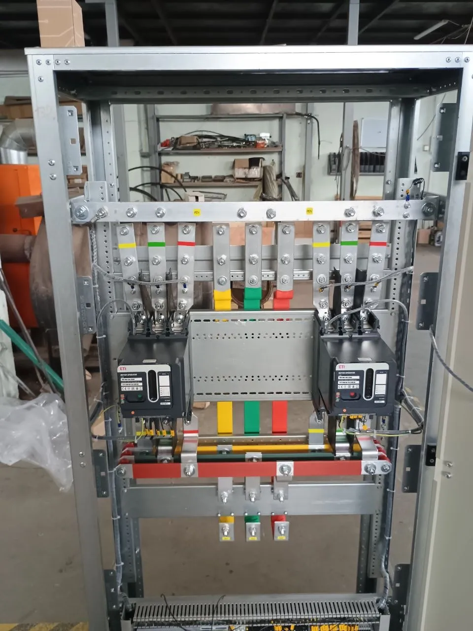
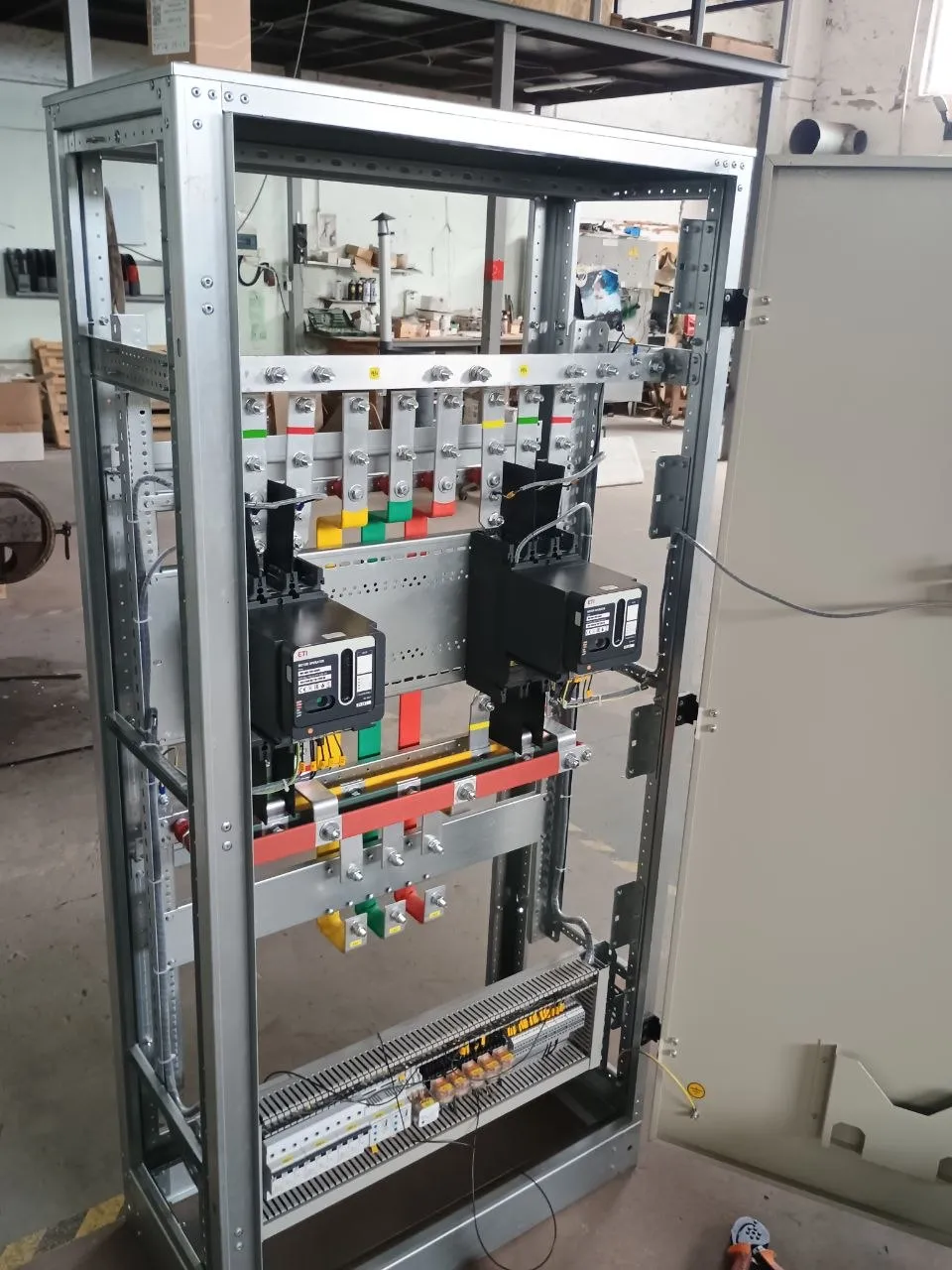
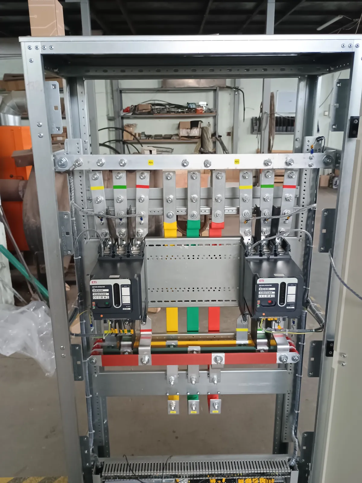
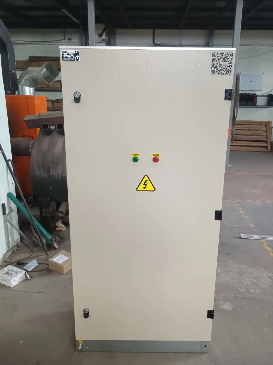
The drawings are provided as a reference standard solution. Site-specific adaptation, load and setting calculations, and compliance with the applicable codes (ПУЕ, ДСТУ, ДБН) are the responsibility of the design engineer. LK Energy Group accepts no liability for use of the solution without adaptation to the conditions of a specific site.
Any questions left?
Write or call us — we answer to the point. Preliminary reply within 24 hours.
+380 67 104 94 91