
General information
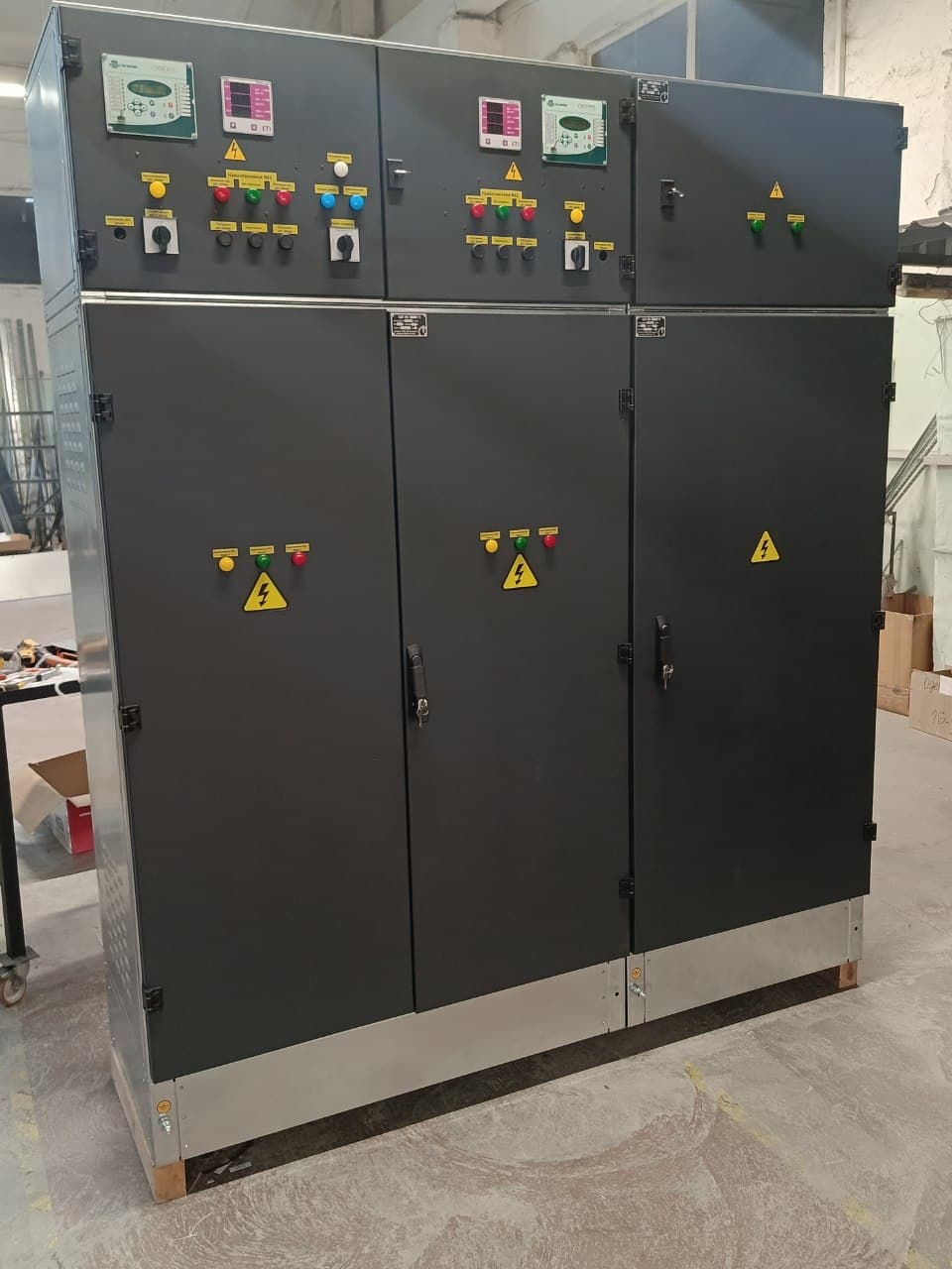
ATS Cabinet — Automatic Transfer to Backup Supply, 0.4 kV
At industrial, medical, transport, educational and other facilities, a stable power supply is critically important. Power interruptions lead to serious consequences, which is why ATS (automatic transfer switch) cabinets are used — they ensure timely switching of the load to the backup source and return to the main source after its parameters are restored. Manufacturing is carried out by LK Energy Group: the process is controlled at every stage, and finished products undergo inspection and testing.
ATS Cabinet: Purpose and Functionality
The device automatically connects the backup source when the voltage on the main input disappears or its parameters go beyond the normal range, and restores power to the main input once it is back to normal. Activation occurs in the following cases:
- loss of voltage on the main input;
- loss or violation of phase sequence;
- voltage parameters going beyond permissible limits;
- emergency short circuit on the main source.
In each of these situations, the ATS cabinet switches the power supply, ensuring system stability. In addition, the device performs monitoring and control of parameters. The main advantage is minimising downtime and the associated financial losses during emergency outages.
Design and Components
The basis of the ATS cabinet is a galvanised steel enclosure (zinc coating mass 275 g/m²) that protects the internal components. Inside are located the control panel, protection devices, contactors, relays, measuring and monitoring instruments, and switching devices. Together they ensure automatic switching and protection of the system against overloads and emergency conditions. Air circuit breakers (ACB) or moulded-case circuit breakers (MCCB) are used as switching devices — the type and ratings are selected on a project-specific basis.
Incoming Devices and Interlocking
Transfer between inputs is performed by contactors, by motor-operated transfer switches or by motor-operated circuit breakers (ACB/MCCB). The choice depends on the protective function required, the expected switching frequency and the calculated current — we select it from the single-line diagram and the technical specification. To prevent two inputs being closed onto common busbars at the same time we provide mechanical and/or electrical interlocking; for schemes with synchronisation the transfer logic is agreed separately.
What the ATS Cabinet Includes
Depending on the scheme, the cabinet includes:
- galvanised steel enclosure with a 275 g/m² zinc coating, built to the project;
- incoming devices — contactors, transfer switches or motor-operated circuit breakers;
- ATS control unit with time delays for transfer and for return;
- mechanical and/or electrical interlocking of the inputs;
- voltage, phase-sequence and phase-failure monitoring relays;
- protective devices for outgoing lines — if the board has them per the scheme;
- measuring instruments and status indication for the inputs;
- circuit marking, product passport and test reports.
Technical Characteristics
| Parameter | Value |
|---|---|
| Rated voltage | 0,4 kV (380/220 V) |
| Rated current | from 100 A; standard solutions 250–630 A; exact rating follows the calculated load |
| Number of inputs | project-specific / per TOR (usually 2, less often 3) |
| IP protection rating | project-specific / per TOR (e.g., IP31 or IP54) |
| Switching logic and time | project-specific / per TOR |
| Enclosure material | galvanised steel, zinc coating 275 g/m² |
Which backup scheme your site uses
| Main source + backup | Switching logic | What we need from you |
|---|---|---|
| Two utility inputs | Transfer to the backup input on loss of voltage, loss or reversal of phase sequence, voltage outside permissible limits, or a short circuit on the main source; return once restored | Single-line diagram or list of loads |
| Utility + diesel generator | The same plus an adjustable time delay for starting the backup source and monitoring the return of the main input | The same plus the desired start-up delays |
| Utility + UPS | Transfer governed by voltage monitoring; the exact switching sequence is agreed to your continuity requirements | The same plus your continuity-of-supply requirements |
| Three inputs (less often) | Logic defined per project / technical specification | Single-line diagram covering all inputs |
Reliability
The enclosure is fully metal, resistant to mechanical impact and moisture, and protects against unauthorised access. The wiring is insulated, markings are applied to the control panel, and the switching devices operate according to the specified logic. Each product is checked for compliance with the TOR requirements.
Manufacturing Lead Time
An ATS cabinet can be ordered to suit the requirements of the facility after the configuration has been agreed with a manager. The average manufacturing lead time is about 2 weeks (depending on complexity and component availability).
Warranty
Warranty — 2 years on the product (extended to 5 years by agreement); galvanised enclosure metalwork — 10 years.
Delivery
Shipping by our own logistics service or self-pickup. Delivery within Ukraine and abroad.
Completed Projects
ATS cabinets have been manufactured, in particular, for hospitals in Odesa and Mykolaiv.
Description and purpose
An ATS (automatic transfer switch) cabinet is a low-voltage 0.4 kV switchboard that automatically transfers the load from the main power source to a backup one (a second input, a diesel generator set, or a UPS) if the voltage disappears or its parameters go out of the normal range, and switches back once it is restored. It is designed for facilities where power interruptions are unacceptable: hospitals, data centers, pumping stations, boiler houses, manufacturing plants, shopping centers. All specifications — the number of inputs and outgoing lines, rated current, IP rating, switching logic and switching time — are selected to match your technical specification (TZ). We build ATS cabinets from 100 A; standard solutions cover 250–630 A, and among completed projects there is a 400 A “grid — diesel generator” ATS. The exact rating follows the calculated load. Manufactured by LK Energy Group, a switchgear manufacturer from Odesa (company since 2005, own factory since 2015): in-house production, inspection of every unit, built to project requirements. Which data we need for a quotation and how to fill out the questionnaire is shown step by step in the article How to Fill Out the Questionnaire for a KTP or KSO.
Standard solution: 0.4 kV ATS — sizing for your facility →
Find the right equipment for your site
Answer them and we will come back with a configuration and a ballpark price for your site.
Grid connection, switchgear and substations made in-house — one contractor for the entire electrical scope of your plant.
FAQ
What is the rated current and how many inputs does the ATS cabinet have?
How fast is the switchover to backup power?
Can an ATS cabinet be ordered to a custom technical specification?
What are the manufacturing lead time and warranty?
Where are ATS cabinets used?
How do I order an ATS cabinet and what is needed for a quotation?
Can an ATS cabinet also work as an incoming and distribution board?
Price request:
Automatic Transfer Switch (ATS) Cabinet
Send us your single-line diagram or specification — we will estimate the configuration, lead time and price. Preliminary estimate within 24 business hours.
+380 67 104 94 91