
AVR panel (ShAVR): how it works and when it is needed
Author of the article: Sviatoslav Yurdyk, Quality Engineer at LK Energy Group.
Responsible for quality control of switchgear at the plant — acceptance testing of NKU assemblies, verification of secondary-circuit diagrams and of AVR automation operation before shipment. Every AVR cabinet has its transfer logic checked on a test bench.
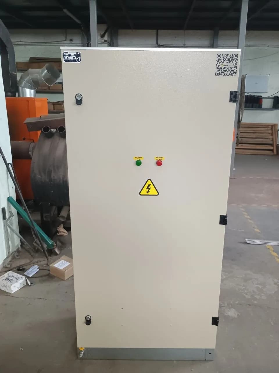
An AVR panel (AVR — automatic transfer switch) is a cabinet with switching devices and automation that supplies loads from the main incomer, continuously monitors the voltage on it and, if that voltage disappears or deviates beyond permissible limits, transfers the load to a backup source on its own — a second incomer from the grid or a diesel genset. In documentation and price lists the same product goes by different names: AVR panel, AVR cabinet, ShAVR — they all mean the same thing. The purpose is one: to cut the supply interruption from hours (waiting for an electrician to arrive and throw the changeover switch) down to seconds, with no human involvement.
How AVR works: two incomers and voltage monitoring
The classic AVR scheme is built around two incomers. Incomer 1 is the main (priority) one, incomer 2 is the backup. In normal operation the load is supplied from the main incomer, while the backup one stands energised and ready.
The automation — a voltage monitoring relay or an AVR controller — watches the main incomer continuously, against several parameters:
- Presence of voltage
- a complete loss of supply is the main trigger scenario.
- Voltage level
- going outside the defined limits (a deep sag or an overvoltage), when loads can no longer be supplied with such voltage.
- Phase status
- a phase loss or asymmetry in a three-phase network — dangerous for motors and other three-phase loads.
When the monitored parameter goes beyond the setpoint, the automation runs through its cycle: time delay (so as not to react to a short dip) → opening of the main incomer device → verification that it has actually opened → closing of the backup incomer device. Once voltage on the main incomer is restored, a scheme with auto-return waits out a pause, makes sure the voltage is stable and transfers the load back; in schemes without auto-return the transfer back is performed by personnel.
When an AVR panel is needed: supply reliability categories under the PUE
The answer comes from the power supply design, via the reliability category under the PUE (Electrical Installation Code):
- Category I
- a supply interruption is permitted only for the duration of automatic restoration — meaning that here AVR is not an option but a mandatory part of the scheme. Supply comes from two independent sources. These are fire protection systems, hospital operating theatres and intensive care units, boiler houses, communication facilities, hazardous production sites.
- Special group of Category I
- loads for which even a short interruption is unacceptable (risk to life, explosion, destruction of equipment). In addition to two incomers, a third independent source is provided — a diesel genset, a UPS or battery banks. Here AVR already manages three sources.
- Category II
- formally the PUE allows switching to be performed by on-duty personnel or a mobile crew. In practice, however, AVR is installed here as well: downtime of a production line, a shop or a pumping station costs more than an automation cabinet.
- Category III
- a single source, with an interruption of up to one day allowed for repairs. AVR is not required — it is installed only if the customer wants it.
A separate typical case is facilities with their own generator: banks, data centres, petrol stations, livestock complexes, cold storage warehouses. Even where the category is formally not the first one, process continuity calls for an automatic transfer to the diesel genset.
Types of AVR: from the grid and from a generator
By backup source, the schemes fall into two large groups.
Grid-to-grid AVR (two incomers from the grid). Both sources are the external grid: two lines from different transformers or different substation sections. The backup incomer is always energised, so the transfer takes seconds. A common option for two-transformer substations is the "two incomers + bus-section device" scheme: normally each section is fed from its own incomer, and if one of them fails the bus-section device ties the sections together.
Grid-to-genset AVR. Here the backup is a diesel genset and the logic is more complex: when the grid fails, the automation issues a start command to the genset, waits for the generator to reach rated speed and voltage, and only then transfers the load. Once the grid returns, there is a transfer back and the generator runs at no load to cool down before shutdown. The supply interruption is longer here (the generator starting time), so for particularly critical loads the scheme is supplemented with a UPS. What this scheme requires from the generator itself is covered in the article AVR and the generator: what a genset needs for an automatic start.
AVR cabinets also differ by the type of switching devices — this determines the current, the service life and the behaviour of the scheme:
| AVR design | Switching devices | Key features | Typical application |
|---|---|---|---|
| Contactor-based, with a voltage monitoring relay | Two contactors with electrical and mechanical interlocking | Fast transfer, simple circuit; the contactors hold the incomer closed by means of the coil | Small and medium facilities, incomers roughly up to several hundred amperes |
| Circuit breakers with motor operators | Two (or three) power circuit breakers with geared motor drives | The device combines switching and protection and withstands high currents; driven by an AVR controller | Building VRU service panels, main distribution boards (GRShch), high-current industrial facilities |
| Motorised changeover switch (transfer switch) | A single device with I–0–II positions | Simultaneous closing of both incomers is ruled out by the design of the device itself | Compact solutions, grid-to-generator AVR |
| Grid-to-genset AVR with a generator controller | Contactors or motorised breakers plus genset start automation | Logic for starting, warm-up, load acceptance and generator cool-down | Facilities with their own diesel genset: hospitals, farms, data centres, petrol stations |
AVR circuit: power circuits and control circuits
Any AVR cabinet consists of two parts, and the quality of the product is determined by both of them.
Power circuits are the current path: incoming devices, busbars, the device of each incomer, outgoing feeders to the load. What matters here is the busbar cross-section, the withstand capability of the devices against short-circuit currents, and the tightening of the contact joints.
Control (secondary) circuits are the "brain": the voltage monitoring relay or controller, auxiliary relays, coil and motor drive circuits, position signalling. It is here that the three things are implemented without which AVR cannot be considered sound:
- Time delay
- the pause between the loss of voltage and the transfer. It desensitises the scheme to short dips and gives the grid automation (APV, auto-reclosing) time to restore the supply — otherwise the panel would "twitch" at every flicker of the lights. The setpoint is defined during commissioning for the specific facility: from fractions of a second to a few seconds, while the return to the main incomer is usually set longer, to make sure the grid is stable.
- Mutual interlocking of the incomers
- the key safety condition. Electrical interlocking (normally closed contacts of one incomer's device in the closing circuit of the other) plus mechanical interlocking of the devices themselves guarantee that the two incomers never close at the same time. Otherwise there would be a back-feed connection of two sources carrying short-circuit currents, or voltage fed from the generator into a grid where a repair crew is working.
- Command execution monitoring
- the backup incomer is closed only after it is confirmed that the main one has opened. If a device gets stuck, the scheme halts the transfer and raises an alarm signal instead of creating a hazardous condition.
Manufacture of AVR cabinets to order
There is no standard cabinet "for every occasion": the AVR scheme depends on the incomer current, the number of sources, the presence of a diesel genset, incomer priority, the need for auto-return, and the design requirements for signalling and remote supervision. Hence the working sequence: single-line diagram or questionnaire → selection of devices and layout → assembly → verification of the transfer logic on a test bench before shipment. We manufacture AVR cabinets at our own plant in Odesa — from compact two-incomer ShAVR units to incoming-distribution panels with an AVR section as part of a main distribution board, to the customer's standard or custom scheme. The list of data needed for a quotation is collected in the article Technical specification for switchboard equipment.
Frequently asked questions
How does an AVR panel differ from a manual changeover switch?
A changeover switch is manual: someone has to come and transfer the load, so the supply interruption lasts as long as it takes that person to arrive. AVR does the same thing automatically in seconds, monitoring voltage around the clock, and it additionally prevents both sources from being closed at the same time.
What time delay is used when transferring to the backup supply?
The setpoint is defined during commissioning: typically from fractions of a second to a few seconds for the transfer to the backup supply — so that the panel does not react to short voltage dips and the grid automation has time to operate. The return to the main incomer is set with a longer pause, to make sure the voltage has recovered and is stable. For AVR with a diesel genset, the genset starting time and the time it needs to reach rated operation are added on top.
Can AVR be arranged between the grid and a generator?
Yes, this is the second most common scheme. When the grid fails, the automation starts the diesel genset, transfers the load to it once it reaches rated operation, and when the grid returns it switches back and lets the generator cool down at no load. A mandatory condition is an interlock that rules out feeding voltage from the generator into the external grid.
LK Energy Group manufactures AVR panels at its own plant in Odesa — grid-to-grid units with two incomers, grid-to-genset schemes, AVR sections within VRU and main distribution boards. Every cabinet has its transfer logic verified before shipment. Ready-made solutions are on the AVR cabinet page; for your project we will prepare a quotation based on the single-line diagram — get in touch with us.
See also
Need an engineer’s advice?
Have a task involving power supply, switchgear or solar plants — write to us and we’ll answer to the point.
+380 67 104 94 91