
Standard Solution: Temporary Construction Site Power Supply Cabinet
Standard solution for a temporary construction site power supply cabinet: 400 A incoming supply, contactor with remote disconnect, 6 branch circuits. PDF is open access, DWG available after registration.
Solution files
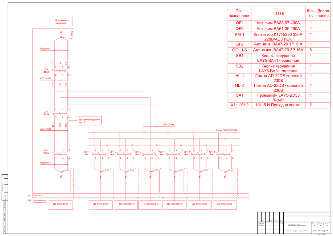
2 PDF · 866 KB — open access- Schematic diagram — main circuitsPDF · 695 KBdiagram
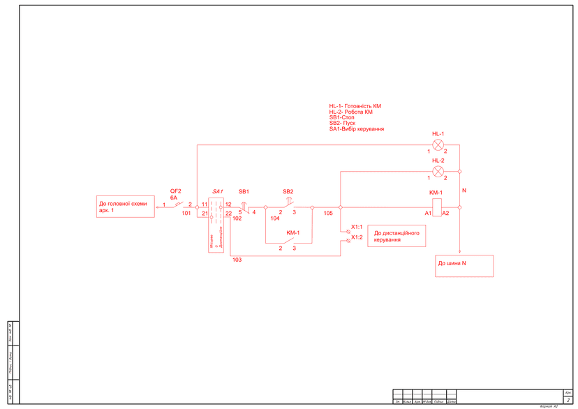
- Control circuit diagramPDF · 172 KBdiagram
DWG set — after a short registration (name, phone, e-mail). The download link appears on screen right after registration and is valid for 7 days.
Get DWGPublished: 11.06.2026 · Author: engineering department of LK Energy Group
Standard solution for a temporary construction site power supply cabinet: 400 A incoming supply, a separate 250 A power circuit through a contactor with local and remote control, and six 16 A branch circuits. The package includes 2 PDF sheets: the schematic diagram of the main circuits and the control circuit diagram. The drawings were produced by LK Energy Group engineers for an actual production order (2022). The PDF is freely available below; the DWG model is available free of charge after a short registration.
How the temporary power supply cabinet is built
During construction, the site is powered under a temporary scheme — until the facility's permanent network is put into operation. The unit that handles this task is the incoming/distribution cabinet: an incoming circuit breaker, a power circuit for the main consumer, and branch circuits for the site's smaller consumers.
This solution has a 400 A incoming supply with the PEN conductor split into PE and N inside the cabinet, and a grounding busbar (galvanized steel strip, 40x4). The main 250 A power circuit is switched by a contactor: it can be switched off with a button on the cabinet or remotely — an "I-0-II" selector switch chooses local or remote control, and the external signal is brought in on terminals X1. The contactor status is shown by "Ready" and "Running" indicator lamps. Six 16 A branch circuits are assembled on a separate busbar and protected by miniature circuit breakers.
Technical parameters of the solution
- Incoming supply: VA88-series incoming circuit breaker, 400 A; fed by a PEN conductor, split into PE and N at the incoming point
- Main consumer power circuit: VA51-39 250 A + KTI-series contactor, 330 A (type per the diagram; 220 V coil, AC3 category), AD31 3x25 busbars
- Contactor control: "Start"/"Stop" buttons (LAY5-BA31/BA41), LAY5-BD33 "I-0-II" selector switch (local/remote), X1:1–X1:2 terminals for the external remote-control circuit
- Signaling: AD-22DS 230 V lamps — green "KM Ready," red "KM Running"; control circuit protection — VA47-29 1P 6 A
- Branch circuits: 6 × VA47-29 3P 16 A on a FORK 3P 63 A busbar
- Busbars: AD31 4x40; PE busbar — galvanized steel strip 40x4, PV3 25 mm² conductor
- Documentation: 2 sheets (A1 + A2), 2022, diagrams in Ukrainian — individual labels of the original in Russian; the ratings for a specific implementation are agreed upon ordering
Package contents and downloads
Preview
DWG package after registration
You get the DWG model of the temporary power supply cabinet (main circuits + control circuits in a single AutoCAD file) free of charge after registration. Registration takes your name, phone and e-mail.
Frequently asked questions
Can this solution be used in my own project?
Yes — as a standard base solution for temporary power supply to a construction site. Adaptation to the specific facility, load calculation, and compliance with the applicable PUE (electrical installation rules)/DSTU (Ukrainian national standards) are provided by the design engineer. The diagrams were produced for an actual LK Energy Group production order from 2022.
What equipment is specified?
A VA88-series incoming circuit breaker, 400 A, a VA51-39 250 A circuit breaker, VA47-29 miniature circuit breakers, a KTI-series contactor, 330 A (type per the diagram), LAY5 buttons and selector switch, AD-22DS indicator lamps. Implementation with other equipment is agreed upon ordering.
How do I get the DWG files?
Click "Get DWG" in the "Solution files" block at the top of the page and complete a short registration (name, phone and e-mail). How you will receive the set is shown in the same block.
Does LK Energy Group manufacture such cabinets?
Yes, we manufacture temporary power supply cabinets and other 0.4 kV switchgear at our own production facility in Odesa; we will help you select equipment ratings for your site's load — +38 067 104 94 91.
See also: standard 0.4 kV ATS solution, ShchO-90 panel for a package transformer substation.
The diagrams are provided as a reference standard solution. Adaptation to the specific facility, verification of protective device selectivity, and compliance with applicable norms (PUE, DSTU, DBN — state building codes) are provided by the design engineer. LK Energy Group is not liable for use of the solution without adaptation to the conditions of a specific facility.
Any questions left?
Write or call us — we answer to the point. Preliminary reply within 24 hours.
+380 67 104 94 91