
DC auxiliary power cabinets (ShOT) — built to project
General information
What a ShOT cabinet is for
A DC auxiliary power cabinet (ShOT, Ukr. ШОТ) is the supply source for the control, protection, automation and alarm circuits of a substation. It is fed from a 220 V, 50 Hz network and delivers DC auxiliary power that does not disappear with the network: while the network is down, the battery carries the load.
Such a board is installed where de-energising the auxiliary circuits is unacceptable: at substations and distribution points with circuit breakers, relay protection and telecontrol, and in the auxiliary supply of industrial sites.
Every cabinet is built for a specific project: its content is set by your auxiliary-supply diagram and the questionnaire.
What is included as standard
- two independent ~220 V inputs with surge protection;
- two rectifiers feeding two DC sections with a common battery;
- a battery in a separate compartment with its own protective device;
- a power-system controller: charging, battery test, event log;
- insulation monitoring of the DC circuits; locating a line with reduced insulation resistance — with portable clamps;
- distribution into groups with individual protective devices;
- voltage and current indication on the door;
- alarm and status output relays to SCADA;
- anti-condensation heating with a thermostat.
What is selected for the project
- the DC voltage and the rectifier power;
- battery capacity for the calculated autonomy time;
- the number and ratings of outgoing groups;
- an auxiliary 24 V / 2.5 A supply, ventilation of the battery compartment, terminals for external signals;
- ingress protection, dimensions and enclosure colour.
The standard content is what both documented cabinets actually had; the final configuration is recorded in the questionnaire and in the circuit diagram that ships with the passport.
What we have built
Delivered work is described by content — by what actually sits inside the cabinets.
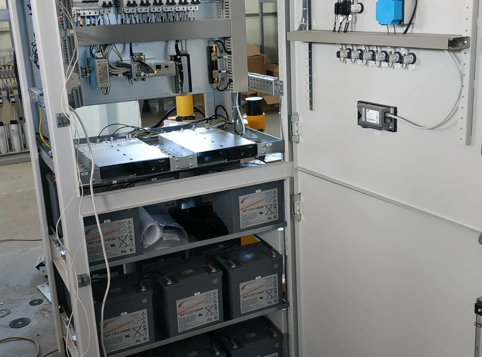
- A 220 V DC cabinet, U3 version, IP31: two rectifiers of 2000 W each, a power-system controller, a device-status and alarm module, two 10 A ammeters and a 250 V voltmeter, a battery of 17 blocks of 12 V / 56.4 Ah in a separate compartment; incoming devices 16 A, battery-circuit devices 63 A.
- A 220 V DC cabinet, U3 version, IP54: the same purpose with a tighter ingress protection, in an enclosure of the same 2200×800×600 mm size.
- The earliest of the three: a DC auxiliary power cabinet tested by an electrical laboratory in 2018.
LK Energy Group has been manufacturing switchboards at its own plant in Odesa since 2015 (the company dates from 2005). Every cabinet leaves the plant with a passport and a circuit diagram; an acceptance test report is provided on request.
What is inside
Cabinet content
The permanent part is the incoming device, the rectifiers, the battery and the distribution into groups. The rest is set by the project.
- Incomer
- two single-phase ~220 V, 50 Hz inputs with surge protection;
- Rectifiers
- two rectifiers feed two DC sections with a common battery: in delivered work 2000 W each, rated output current of the cabinet 16 A at 230 V at the rectifier output;
- Battery
- a separate compartment in the lower part of the cabinet with its own protective device; in delivered work — 17 blocks of 12 V / 56.4 Ah;
- Monitoring
- a power-system controller and a device-status and alarm module: charging, battery test, insulation monitoring, alarm signals;
- Indication
- two 10 A ammeters (the current of each section) and a 250 V voltmeter on the door;
- Heating
- anti-condensation heaters with a thermostat and a manual/auto selector — in both delivered cabinets, with an «heating on» lamp on the door;
- To project
- an auxiliary 24 V / 2.5 A supply, ventilation of the battery compartment, terminals for external signals.
Why the battery sits apart
A battery lives by its own rules: it needs ventilation, access for inspection and replacement, and its own protective device. That is why our cabinets give it a separate compartment with shelves, while the power and control parts are assembled above — servicing one part does not mean reaching into the other.
Autonomy time is a calculation: the load current of the auxiliary circuits, the permissible voltage drop and the battery capacity. We calculate it from your data at the questionnaire stage and select the capacity accordingly.
Battery capacity is calculated for the temperature at the installation site: in the cold a battery delivers less, so for unheated rooms and outdoor sites we provide compartment heating and check the capacity against the actual temperature.
The auxiliary-supply diagram comes from the customer or the design engineer; we build the cabinet to it and issue the as-built circuit diagram together with the product passport.
Specifications
Main parameters
The table shows the parameters of delivered work; for your project they are selected anew.
| Parameter | Value |
|---|---|
| AC supply, V / Hz | 220 / 50; in delivered work — two single-phase inputs with surge protection |
| DC auxiliary output voltage, V | 220 in delivered work; other voltages — to project |
| Rectifiers | to project; in delivered work — two of 2000 W each (up to 4000 W together); rated output current of the cabinet 16 A at 230 V at the rectifier output |
| Device ratings, A | in delivered work — incoming devices 16 A, battery-circuit devices 63 A |
| Battery | to the calculated autonomy time; in delivered work — 17 blocks of 12 V / 56.4 Ah |
| Monitoring and alarms | power-system controller, device-status and alarm module, two 10 A ammeters and a 250 V voltmeter |
| Ingress protection | by installation site; in delivered work — IP31 and IP54 |
| Dimensions H×W×D, mm | 2200×800×600 in delivered work (per the drawing); other sizes — to project |
| Weight, kg | by the set of devices and the battery; in delivered work — up to 700 |
| Climatic version | U3 for indoor use — both documented cabinets; an outdoor version — to a separate specification |
| Ambient air temperature | from −40 to +40 °C; battery capacity is calculated for the actual site temperature |
| Ambient environment | non-explosive, non-flammable |
| Installation altitude above sea level | up to 1000 m |
| Relative humidity | up to 80 % at +20 °C |
Final values are agreed at the questionnaire stage.
Versions and scope of supply
Scope of supply
- the DC auxiliary power cabinet according to the contract and the questionnaire — 1 pc;
- product passport — 1 pc;
- circuit diagram — 1 pc.
An acceptance test report is available on request.
What is selected for the project
- the DC voltage and the rectifier power;
- battery capacity for the calculated autonomy time;
- the number and ratings of outgoing groups;
- insulation monitoring of the DC circuits;
- door indication and the set of signals sent to SCADA;
- ingress protection, dimensions and enclosure colour — to order.
How to order
For a quotation send the list of DC consumers and the required autonomy time: what is fed from the cabinet, the current in normal operation and at breaker closing, and where the cabinet is installed.
The lead time is quoted together with the price, after the questionnaire: it depends on the set of devices and their availability.
Not intended for operation
- in environments with conductive dust, caustic vapours and gases that destroy metal and insulation;
- in places subject to heavy shaking, vibration and impacts;
- on mobile installations.
Warranty
Product warranty — 2 years (extended to 5 years by agreement); enclosure metalwork — 10 years*. The design service life to write-off is 25 years, provided that components with a shorter service life are replaced.
*Indicative terms and conditions. The exact warranty period is stated in the supply contract.
Description and purpose
A DC auxiliary power cabinet (ShOT) is the supply source for control, protection, automation and alarm circuits. It is fed from a 220 V, 50 Hz network; the rectifiers carry the load and charge the battery, and when the network fails the battery takes the load over, so the auxiliary circuits stay energised. In delivered work: a 220 V DC cabinet in the U3 version with IP31 — two rectifiers of 2000 W each (rated output current 16 A at 230 V at the rectifier output), a power-system controller, two 10 A ammeters and a 250 V voltmeter, a battery of 17 blocks of 12 V / 56.4 Ah in a separate compartment, incoming devices 16 A and battery-circuit devices 63 A; a second cabinet in the U3 version with IP54 of the same 2200×800×600 mm size; a third cabinet was tested by an electrical laboratory in 2018. Rectifier power, battery capacity and the number of groups are selected from your auxiliary-supply diagram. Built at our own plant in Odesa; every cabinet ships with a passport and a circuit diagram. Price on request.
Find the right equipment for your site
Answer them and we will come back with a configuration and a ballpark price for your site.
FAQ
How does a DC auxiliary cabinet differ from an uninterruptible power supply?
How long does the cabinet hold without the network?
Is the battery included?
What ingress protection is available and where can it be installed?
Can the cabinet be built to our own set of devices?
Price request:
DC auxiliary power cabinets (ShOT) — built to project
Send us your single-line diagram or specification — we will estimate the configuration, lead time and price. Preliminary estimate within 24 business hours.
+380 67 104 94 91