
Standard Solution: 10 kV KSO Switchgear Cubicles with VV/TEL Breakers and RS83-AV2
Standard solution: 10 kV KSO switchgear cubicles with VV/TEL breakers and RS83-AV2 — 34 sheets of protection and automation (relay protection) diagrams, ATS-SN (automatic transfer switch for auxiliary supply), inspection sheet. PDF openly available, DWG set after registration.
Solution files
9 PDF · 10 MB — open access- Full set in a single PDF (34 sheets)PDF · 4.8 MBalbum34 sh.
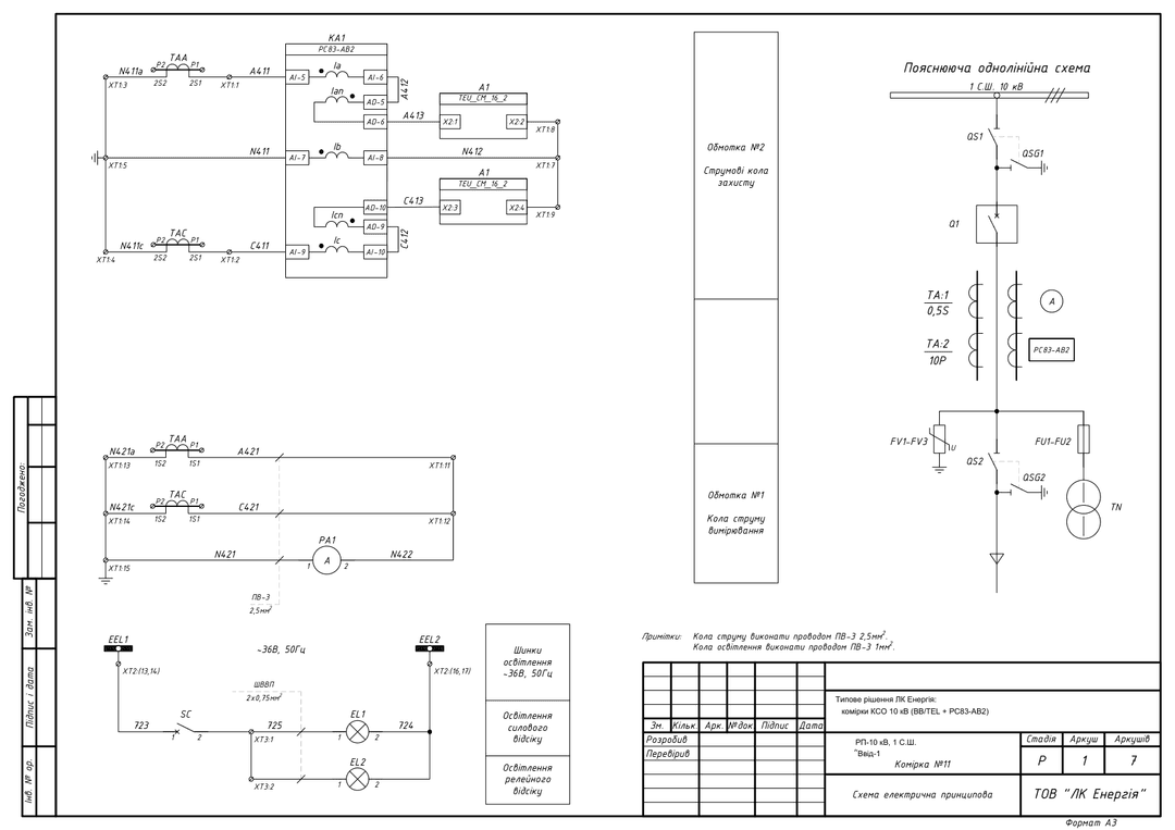
- Incoming feeder 1, Bus Section 1PDF · 751 KBdiagram7 sh.
- Incoming feeder 2, Bus Section 2PDF · 751 KBdiagram7 sh.
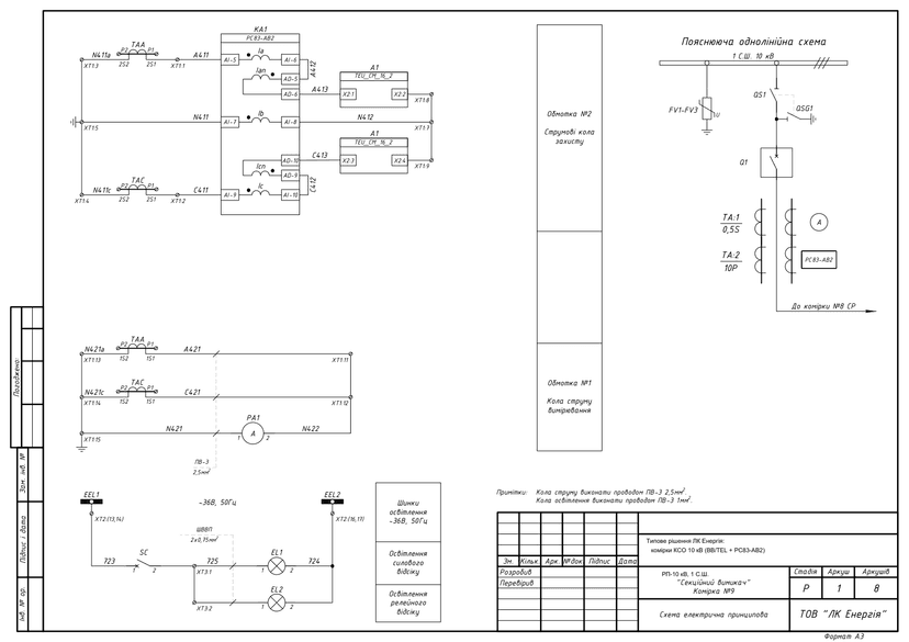
- Bus-section breakerPDF · 766 KBdiagram8 sh.
- Outgoing line, Bus Section 1(2)PDF · 735 KBdiagram6 sh.
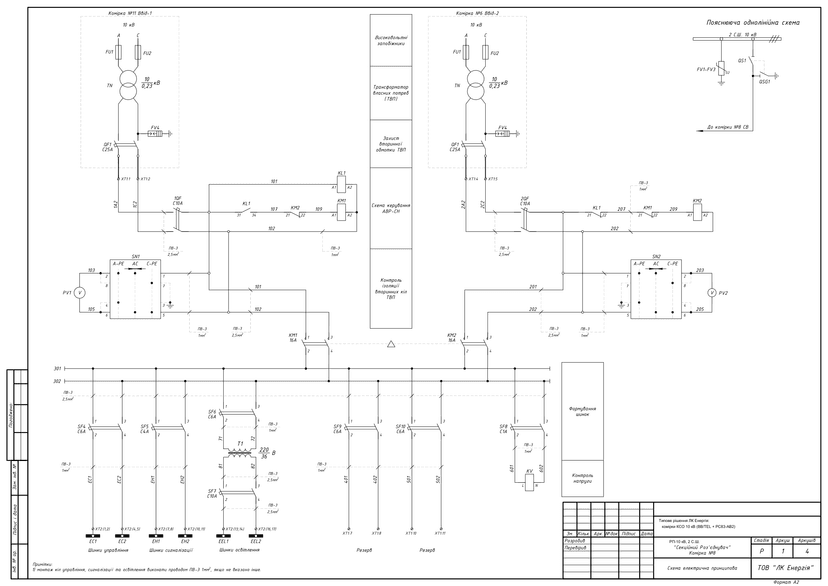
- Bus-section disconnector + ATS-SNPDF · 792 KBdiagram4 sh.
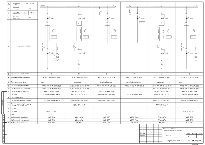
- Inspection sheetPDF · 607 KBquestionnaire1 sh.
- Inter-cubicle connectionsPDF · 594 KBdiagram1 sh.
- Equipment layout planPDF · 597 KBdrawing1 sh.
DWG set — after a short registration (name, phone, e-mail). The download link appears on screen right after registration and is valid for 7 days.
Get DWGPublished: 11.06.2026 · Author: Engineering Department, LK Energy Group
A ready-made set of Design-stage (Stage P) relay protection and automation schematic diagrams for a section of 10 kV KSO switchgear cubicles built on VV/TEL vacuum circuit breakers (VV/TEL-10/630-20U3) with RS83-AV2 microprocessor-based protection terminals: 34 sheets — two incoming feeders, a bus-section breaker, outgoing feeder lines, a bus-section disconnector with an auxiliary-supply automatic transfer switching circuit (ATS-SN), an inspection sheet, and inter-cubicle wiring connections. The diagrams were developed by LK Energy Group engineers for an actual reconstruction project of an operating substation (2024). The PDF is freely available below; the DWG set is available after a short registration.
How the VV/TEL design differs
This solution is a variant of our baseline set "10 kV Distribution Point on KSO Cubicles", which explains what a 10 kV distribution point (RP-10 kV) is and when a dual-bus-section scheme is used. Here, the same task is solved on a different hardware platform and for a different scenario:
- VV/TEL switching instead of VV-N10
- Control and signaling circuits are adapted for the VV/TEL-10/630-20U3 circuit breaker drive.
- Reconstruction of an operating substation, not a new distribution point
- A compact configuration of 6 KSO cubicles of the KSO-E series (two incoming feeders, two outgoing lines, a bus-section breaker, a bus-section disconnector) across two bus sections.
- Auxiliary supply without separate auxiliary-transformer cubicles
- OLSPU-2.5-10 U2 auxiliary supply transformers are housed within the incoming-feeder cubicles, while the bus-section disconnector cubicle implements an auxiliary-supply automatic transfer switch (ATS-SN) with insulation monitoring of the auxiliary transformer's secondary circuits.
- No commercial metering unit
- metering circuits were not provided for in this design. If an AMR/ASKOE (automated commercial electricity metering system) metering unit with voltage-transformer cubicles is required, see the flagship solution.
Technical parameters of the solution
- Rated voltage: 10 kV, two bus sections; 630 A busbars (AD31 5×50)
- Rated breaking current: 20 kA
- Cubicles: KSO series KSO-E, busbar and line disconnectors RR/EL-RR-OZ-10-630(1000)-25U2
- Switching: VV/TEL-10/630-20U3 vacuum circuit breakers
- Protection: RS83-AV2 microprocessor-based terminals
- Measurement: TOLU-10 current transformers with 0.5S/10P windings (300/5 for incoming feeders and the bus-section breaker, 200/5 for outgoing lines), TZLU-125-1 30/1 zero-sequence current transformers on outgoing lines
- Overvoltage protection: OPN-10/12/10/550 UHL1 surge arresters
- Auxiliary supply: OLSPU-2.5-10 U2 auxiliary transformers in incoming-feeder cubicles + ATS-SN
- Control circuits: control and signaling at ~220 V 50 Hz, compartment lighting at ~36 V
- Year developed: 2024, Design Stage (Stage P), diagram language — Ukrainian, format DWG (AutoCAD)
- Parameters of a specific implementation (rated currents, cubicle types) are agreed upon via the inspection sheet
Set contents and downloads
| No. | Function | Cubicle | Equipment | Sheets | Diagrams |
|---|---|---|---|---|---|
| 1 | Incoming feeder 1, Bus Section 1 | Cubicle No. 11 | VV/TEL, RS83-AV2, TOLU-10 0.5S/10P-300/5, OLSPU-2.5-10 | 7 | |
| 2 | Incoming feeder 2, Bus Section 2 | Cubicle No. 6 | VV/TEL, RS83-AV2, TOLU-10 0.5S/10P-300/5, OLSPU-2.5-10 | 7 | |
| 3 | Bus-section breaker | Cubicle No. 9 | VV/TEL, RS83-AV2, TOLU-10 0.5S/10P-300/5 | 8 | |
| 4 | Outgoing line, Bus Section 1(2) | Cubicle No. 10 (No. 7) | VV/TEL, RS83-AV2, TOLU-10 0.5S/10P-200/5, TZLU-125-1 | 6 | |
| 5 | Bus-section disconnector + ATS-SN | Cubicle No. 8 | ATS-SN, auxiliary transformer circuit insulation monitoring | 4 | |
| 6 | Inspection sheet (KSO-E-10-393) | — | Single-line diagrams of all 6 cubicles | 1 | |
| 7 | Inter-cubicle connections | — | Cable connections for control and signaling circuits | 1 | |
| 8 | Equipment layout plan | — | Layout plan of the distribution-point room with cubicle placement | 1 |
The sections for breaker cubicles contain schematic diagrams of protection and measurement circuits, control and signaling circuits, compartment lighting circuits, and an explanatory single-line diagram.
Diagram previews
DWG set after registration
You get the full DWG set (Incoming Feeder 1, Incoming Feeder 2, bus-section breaker, outgoing line, bus-section disconnector, inspection sheet, inter-cubicle connections) free of charge after registration. Registration takes your name, phone and e-mail.
Frequently asked questions
How does this solution differ from the VV-N10 design?
The baseline protection and automation circuit design on RS83-AV2 terminals is the same, but the control circuits are adapted for the VV/TEL vacuum circuit breaker drive, the configuration is more compact (6 cubicles for reconstructing an operating substation), and auxiliary supply is implemented using OLSPU auxiliary transformers with ATS-SN instead of separate auxiliary-transformer cubicles. The full baseline set on VV-N10 (108 sheets, with voltage transformers and an AMR/ASKOE metering unit) is available on the flagship solution page.
Can these diagrams be used in a working design project?
Yes — as a standard baseline solution. Site-specific adaptation, relay protection setting calculations, the cable schedule, and compliance with the applicable PUE (electrical installation rules) / DSTU (Ukrainian national standards) are the responsibility of the design engineer. The diagrams correspond to an actual reconstruction project for an operating substation, developed in 2024.
How can I get the DWG files?
Click "Get DWG" in the "Solution files" block at the top of the page and complete a short registration (name, phone and e-mail). How you will receive the set is shown in the same block.
Does LK Energy Group manufacture KSO cubicles to these diagrams?
Yes. We manufacture KSO/KRU switchgear cubicles, RUNN low-voltage distribution cabinets, and ShchO-90 panels at our own production facility in Odesa — over 3,000 units of equipment manufactured since 2015. We can help adapt the solution and fill out the inspection sheet: +38 067 104 94 91.
Delivered project: 10 kV switching station with telecontrol, Zaporizhzhia
Delivered project: 10 kV switchgear on six KSO-E cubicles with vacuum breakers (Chornomorsk)
The diagrams are provided as a reference standard solution. Site-specific adaptation, relay protection setting calculations, and compliance with applicable standards (PUE, DSTU, DBN — state building codes) are the responsibility of the design engineer. LK Energy Group is not liable for use of the solution without adaptation to the conditions of a specific site.
Any questions left?
Write or call us — we answer to the point. Preliminary reply within 24 hours.
+380 67 104 94 91