
Standard Solution: YAVU — 0.4 kV Service Entrance and Metering Cabinet
Standard wiring diagrams for the YAVU — 0.4 kV service entrance and metering cabinet: overhead-line supply, GAMA300 metering via current transformers, IP54. PDF freely available, DWG after registration.
Solution files
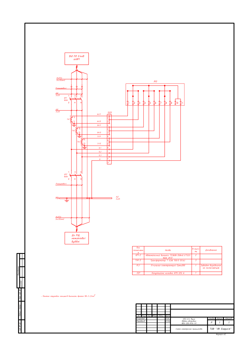
2 PDF · 214 KB — open access- YAVU-250-IP54-U1 — schematic wiring diagram (base version)PDF · 107 KBdiagram
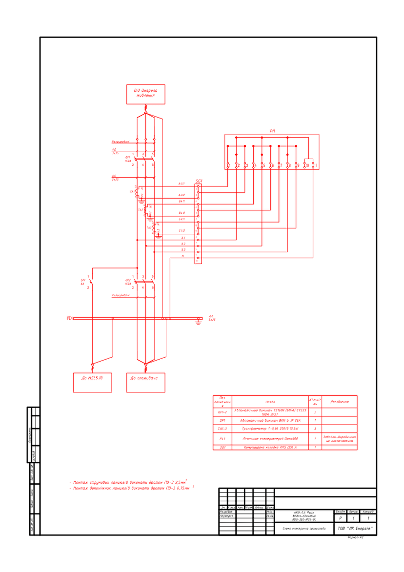
- YAVU-250-IP54-U1 with MSL5.10 circuit — schematic wiring diagramPDF · 107 KBdiagram
DWG set — after a short registration (name, phone, e-mail). The download link appears on screen right after registration and is valid for 7 days.
Get DWGPublished: 11.06.2026 · Author: Engineering Department, LK Energy Group
Two verified schematic diagrams of the YAVU-250-IP54-U1 service entrance and metering cabinet, from actual LK Energy Group orders placed in 2023: a base version with supply from a 0.4 kV overhead line, and a version with an additional power circuit for an MSL5.10 data acquisition device. Each sheet includes a complete bill of materials — circuit breakers, current transformers, meter, test terminal block. The PDF is freely available below; the source drawing files (DWG) are available after a short registration.
What a YAVU is and where it is used
A YAVU (service entrance and metering cabinet) is a 0.4 kV low-voltage assembly (LVA) that combines an incoming switching device and a commercial electricity metering unit in a single enclosure. In its standard configuration, the YAVU receives power from a 0.4 kV overhead line, passes it through an incoming circuit breaker and current transformers to the meter, and delivers it via an outgoing breaker to the consumer building's distribution board.
The YAVU-250-IP54-U1 version is designed for outdoor installation (U1) with an IP54-rated enclosure: the cabinet is placed at the boundary of balance-sheet ownership — near an overhead-line pole or on the facade or plinth of a building — wherever grid operator personnel need access to the metering unit. Metering is performed with a transformer-connected GAMA300 meter fitted with a KP5 test terminal block, which allows the meter to be replaced without de-energizing the consumer.
LK Energy Group has been series-manufacturing YAVU service entrance and metering cabinets since 2015; per order data sheets from 2021–2024, versions have been produced for rated currents from 63 to 500 A, including two-section units (2YAVU-250).
Technical parameters of the solution
- Rated voltage of main circuits: 380 V, 50 Hz
- Configuration as supplied: YAVU-250-IP54-U1 — outdoor installation, IP54 enclosure
- YAVU-250 dimensions (per data sheet): 1200×600×450 mm + 300 mm plinth, mass up to 100 kg
- Switching devices in the diagrams shown: 2 × TS160N (50 kA) ETS23 160 A 3P3T circuit breakers (incoming + outgoing); device ratings to be specified per order
- Metering: transformer-connected GAMA300 meter (not supplied by the manufacturer as part of the wiring scheme — installed by the distribution system operator or the owner under contract), T-0.66 150/5 or 200/5 current transformers (class 0.5S), KP5 test terminal block
- MSL5.10 version — with a data acquisition device (on order): additional BKN-b 1P C6A modular breaker and a power supply tap for the device
- Input/output: АsXSn 4×35 mm² cable (from the 0.4 kV overhead line and to the building's distribution board); current-circuit wiring — PV-3 2.5 mm²
- Manufactured per GOST 22789-94; climatic version U, temperature range −40 to +40 °C
- Design stage: R (working documentation); A2-format sheets, language — Ukrainian, developed in 2023
- Specific configuration (rating, supply method, metering scheme) — per the technical questionnaire
Package contents and downloads
| No. | Document | Contents | File |
|---|---|---|---|
| 1 | YAVU-250-IP54-U1 — schematic wiring diagram (base version) | Supply from a 0.4 kV overhead line, output to the building's distribution board; TS160N 160 A ×2, CT 150/5, GAMA300, KP5 terminal block, bill of materials | |
| 2 | YAVU-250-IP54-U1 with MSL5.10 circuit — schematic wiring diagram | Same as above + BKN-b 1P C6A breaker and power supply tap for the MSL5.10 device; CT 200/5 |
Preview
DWG after registration
You get the source files of the diagrams (DWG, AutoCAD) free of charge after registration; one of the source files also includes the 0.4 kV UKM (capacitor bank unit) diagram. Registration takes your name, phone and e-mail.
Frequently Asked Questions
Can these diagrams be used in a working design project?
Yes — as a standard baseline solution. Site-specific adaptation, selection of device ratings, verification of protection selectivity, and compliance with the applicable PUE (electrical installation rules) and DSTU (Ukrainian national standards) are the responsibility of the design engineer. The diagrams correspond to actual orders manufactured by LK Energy Group in 2023.
How do I select the right YAVU configuration?
Via the technical questionnaire: rated current, supply method (overhead or cable), metering scheme (direct or transformer connection), enclosure protection rating, and installation location. Per order data sheets from 2021–2024, versions from 63 to 500 A have been manufactured, including two-section units (2YAVU-250).
What equipment is specified in the diagrams?
TS160N (50 kA) 160 A circuit breakers, T-0.66 current transformers (class 0.5S), a GAMA300 meter, and a KP5 test terminal block. For versions with other equipment — please contact us.
How can I get the DWG files?
Click "Get DWG" in the "Solution files" block at the top of the page and complete a short registration (name, phone and e-mail). How you will receive the set is shown in the same block.
Does LK Energy Group manufacture YAVU units to these diagrams?
Yes. We manufacture YAVU service entrance and metering cabinets in series production since 2015 at our own facility in Odesa. We will help you select the right configuration and complete the technical questionnaire: +38 067 104 94 91.
See also: standard solution for a 10/0.4 kV KTP (package transformer substation) with low-voltage switchgear, ShchO-90 switchboard for a package transformer substation (ZTP).
These diagrams are provided as a reference standard solution. Site-specific adaptation, verification of protective device selectivity, and compliance with applicable codes (PUE, DSTU, DBN — state building codes) are the responsibility of the design engineer. LK Energy Group is not liable for the application of this solution without adaptation to the conditions of a specific site.
Any questions left?
Write or call us — we answer to the point. Preliminary reply within 24 hours.
+380 67 104 94 91