
KSO-E Type Single-Front-Access Switchgear Cabinets, Assembled (Dimension 393)
General information
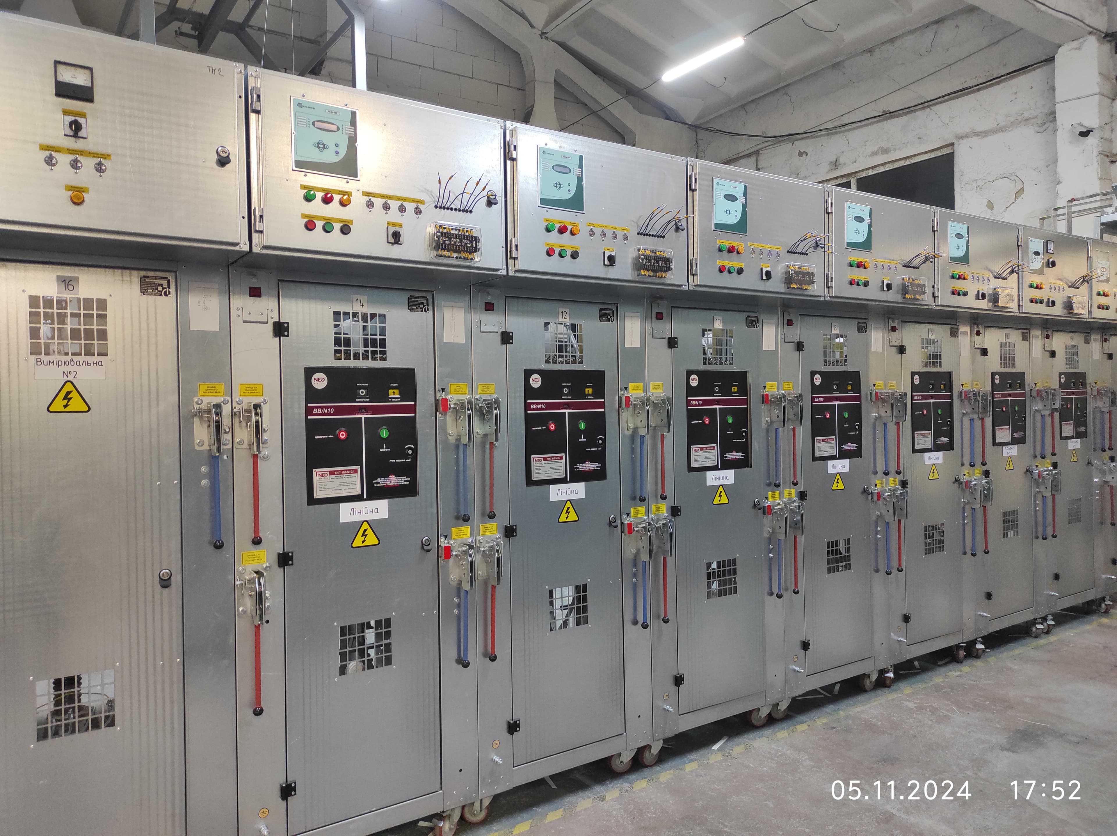
KSO-E prefabricated front-access switchgear cells
KSO-E cells are designed for receiving and distributing three-phase 50 Hz AC electricity in networks with an isolated neutral or a neutral grounded through an arc-suppression reactor. LK Energy Group manufactures KSO-E in series for 6, 10 and 20 kV; versions for 35 kV are made to order according to technical conditions (short-circuit currents and ratings for this class are determined project-specific/TS). Switching is vacuum-type; there is no SF6 gas-insulated version. The enclosure is a prefabricated riveted structure made of galvanized cold-formed profiles, with optional powder coating per RAL.
The cells are equipped with main devices and protection elements according to the order specification; secondary circuit schemes are developed for each individual project. Manufactured to our own technical specifications.
Technical characteristics (serial design 6 / 10 / 20 kV)
| Parameter | Value |
|---|---|
| Rated voltage | 6 / 10 / 20 kV (serial); 35 kV (to order per TU) |
| Highest operating voltage | 7.2 / 12 / 24 kV (serial); 40.5 kV (to order) |
| Rated current of main circuits (6 / 10 / 20 kV) | 630 / 1000 A |
| Electrodynamic withstand of main circuits (6 / 10 kV) | 51 kA (63 kA at 10 kV) |
| Thermal withstand of main circuits, 3 s (6 / 10 kV) | 20 kA (25 kA at 10 kV) |
| Short-circuit currents for 20 kV; rated current and short-circuit currents for 35 kV | project-specific / TS |
| Switching type | vacuum circuit breaker (type project-specific) |
| Design (dimensions) | KSO-393 / 393V / 393VM / 393M-V / 272 / 285 / 20 / 219 / 35; narrow "U" — 650 mm |
| Regulatory basis | Manufacturer's own technical specifications |
KSO or KRU: which to choose for a 6–10 kV switchboard
| Feature | KSO-E | KRU |
|---|---|---|
| Access | single-front, from the front | double-side |
| Main devices | fixed | withdrawable trucks |
| Footprint and cost | more compact and cheaper | less compact and more expensive |
| Typical use | indoor installation in enclosed switchgear / transformer substations | facilities that require redundancy |
| Switching | vacuum circuit breakers and disconnectors; no SF6 design | no data on this page |
Which KSO-E scheme your site needs
| Task on site | Schemes of the range | Dimensions |
|---|---|---|
| Feed in or take off a line, switching without load | 01 · 02 (disconnector) | 1900 × 800 × 800; 02V — 2200 |
| Switch a connection on and off under load | 03 · 04 (switch-disconnector, with PKT fuses in 04) | 1900 × 800 × 800; "V" — 2200 |
| Metering or protection supply required | 05 · 06 (TOL current transformer) | 1900 × 800 × 800 |
| Voltage measurement / voltage transformers required | 07 · 08 · 09 · 11 · 13 | 1900 × 800 × 800; "V", "S" — 2200 |
| Auxiliary supply for the site required | 12 · 23 (OMP/OLS/TMG/TSLU transformer, 10–40 kVA) | 12 — 2200; 23 — 1900, "V"/"S" — 2200 |
| Short-circuit current switching required | 14 · 17 · 18V · 19V · 20V · 21V (vacuum circuit breaker, BB/TEL) | 2200 × 800 × 800 |
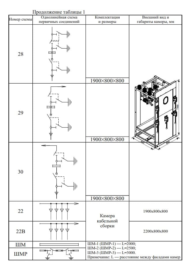
| Bus-section, earthing | 28 · 29 · 30 · 15L · 15P | 1900 × 800 × 800 |
| Cable termination, joining rows | 22 · 22V · ShM / ShMR busbar bridge (L = 2000 / 2500 / 3000 mm) | 1900 and 2200 × 800 × 800 |
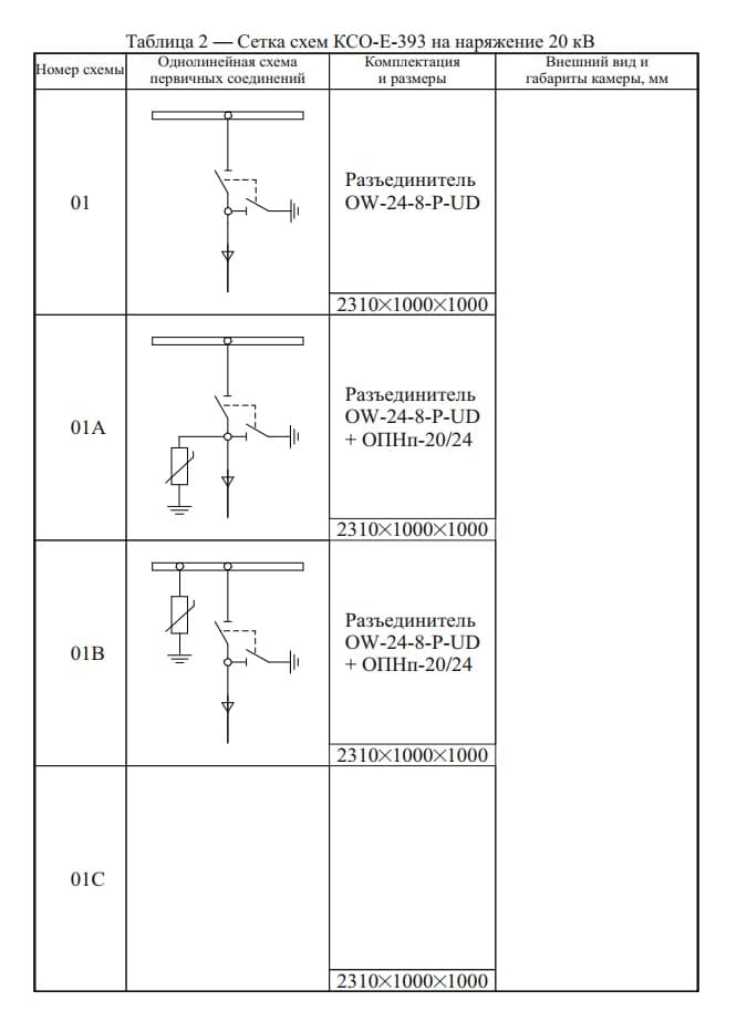
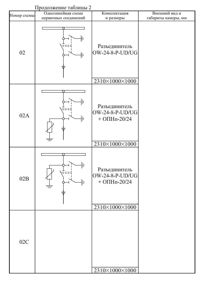
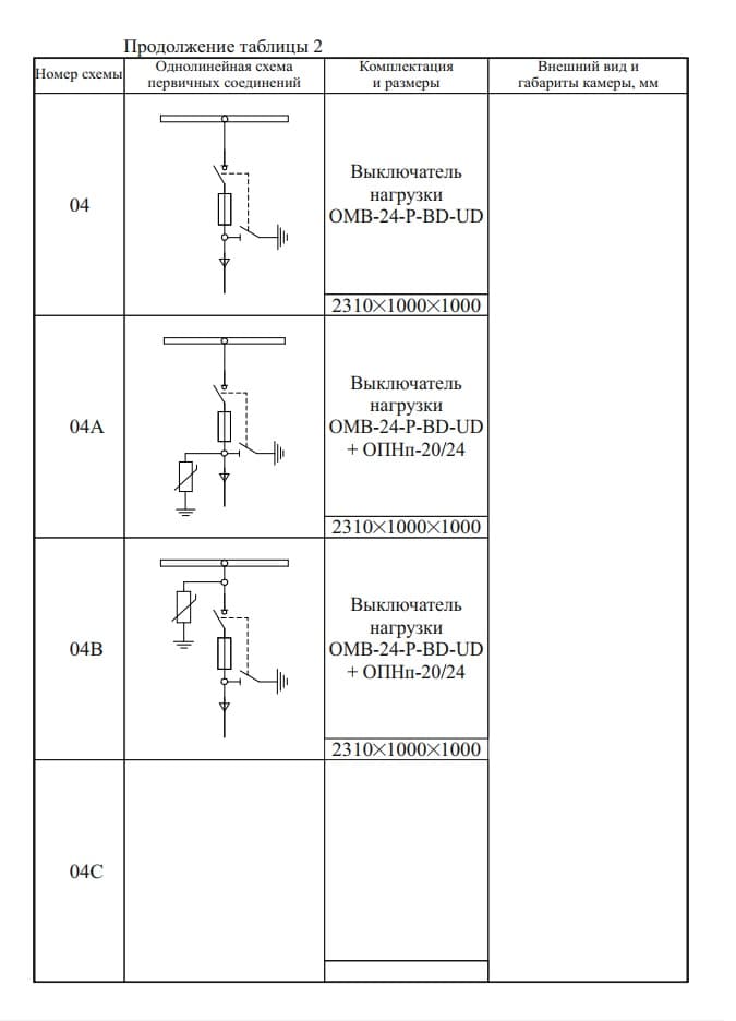
| The same, but the 20 kV class | a range of its own at 20 kV (01–06, 12, 14, 17V, 22P/22L) | frame 7 — 2310 × 1000 × 1000 |
The exact designation is confirmed against your single-line diagram: send it or a completed questionnaire. Together with the diagram we need the voltage class (6, 10 or 20 kV) and the main-circuit current — 630 or 1000 A.
Specific main circuit schemes, devices, and dimensions are selected for your project. Send us an inquiry sheet — we will prepare a solution.
Schemes: main-circuit arrangements
You do not have to find your scheme in this list — we build any of them. Over eleven years of in-house manufacturing we have built every scheme in the series, and we build any of them today: at 6, 10 and 20 kV, with main-circuit currents of 630 and 1000 A. From the simplest cubicle with a disconnector through to one with a vacuum circuit breaker, a metering cubicle with voltage transformers, and an auxiliary-supply cubicle with a built-in 10–40 kVA transformer.
If your specification carries a scheme with a letter — 03A, 11V, 17V — that is the same scheme in a variant, and it is ours too. The exact designation is confirmed against your single-line diagram: send it to us, or send a completed questionnaire.
How the designation reads
The full designation of a cubicle looks like this:
KSO-E-393-17V / 20 / 0,63 U3
| Part | Meaning |
|---|---|
| KSO-E | single-side-access assembled cubicle |
| 393 | frame (enclosure type) |
| 17V | main-circuit scheme number — this is the variant |
| 20 | rated voltage, kV |
| 0,63 | rated main-circuit current, kA (0.63 or 1.0) |
| U3 | climatic design and location category to GOST 15150-69 |
Specifications and passports often record the same cubicle differently — KSO-E-393 17V/10/630-393V, with the current in amps and the frame repeated at the end. It is the same product.
Schemes at 6 and 10 kV
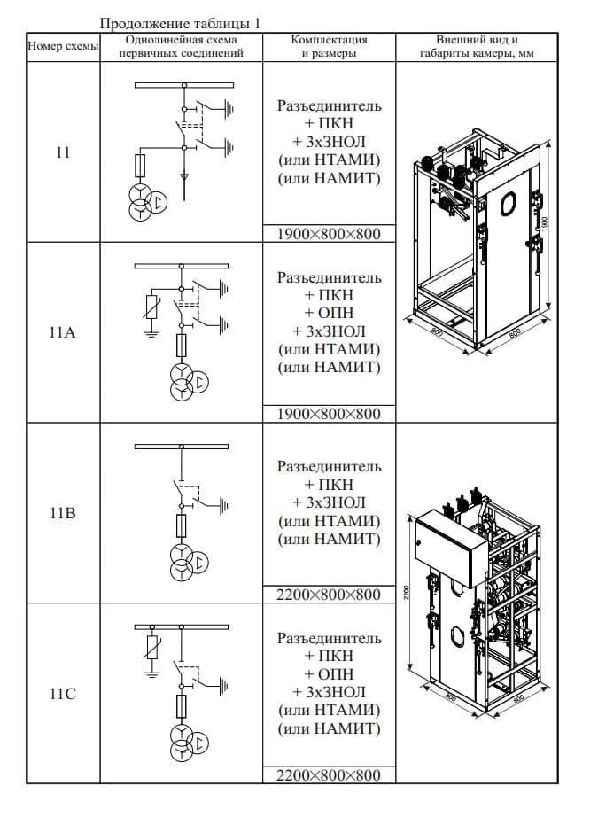
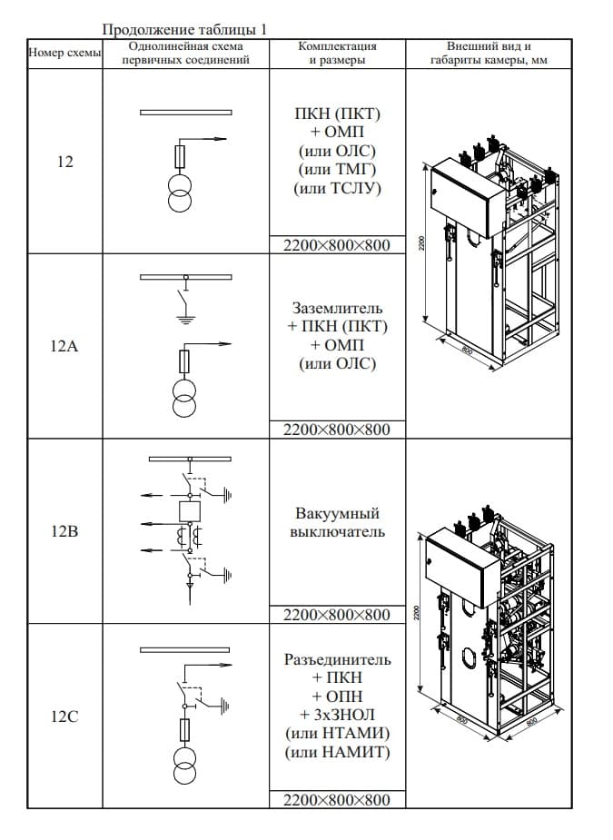
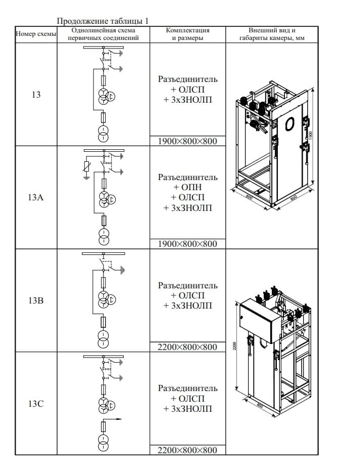
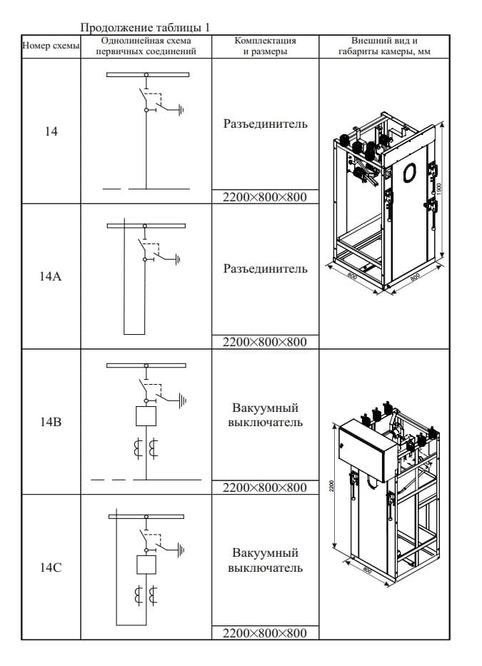
Dimensions are given as H × W × D, mm. The letters A / V / S denote variants of the same scheme: typically a surge arrester is added and/or the cubicle height changes.
Dimensions by version
| Version | Dimensions (H × W × D), mm |
|---|---|
| KSO-E-393 | 1900 × 800 × 800 |
| KSO-E-393V | 2200 × 800 × 800 |
| KSO-E-393VM | 2400 × 800 × 800 |
| KSO-E-393M/V | 2200 × 650 × 800 |
| KSO-E-272 | 2920 × 1000 × 1200 |
| KSO-E-285 | 2770 × 1000 × 1100 |
| KSO-E-393 for 20 kV | 2100 × 1000 × 1000 (enclosure; 2310 with top bushings) |
Overall dimensions may be adjusted to order (catalogue note).
Incomers and feeders with a disconnector
| Scheme | What it does in the circuit | Dimensions |
|---|---|---|
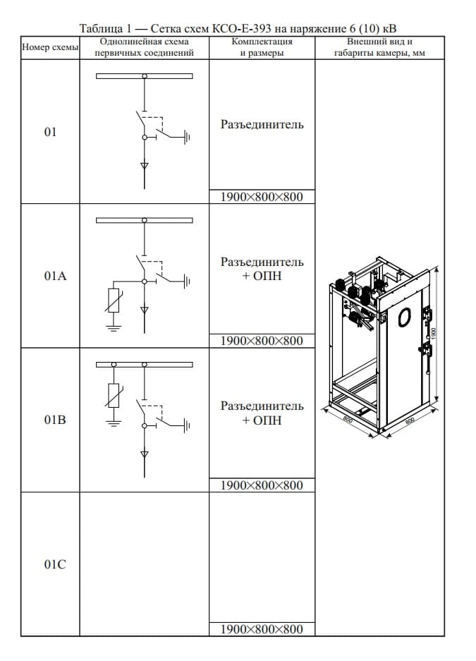
| 01 · 01A · 01V · 01S | Incomer or feeder with a disconnector — the simplest cubicle in the row; the variants add a surge arrester | 1900 × 800 × 800 |
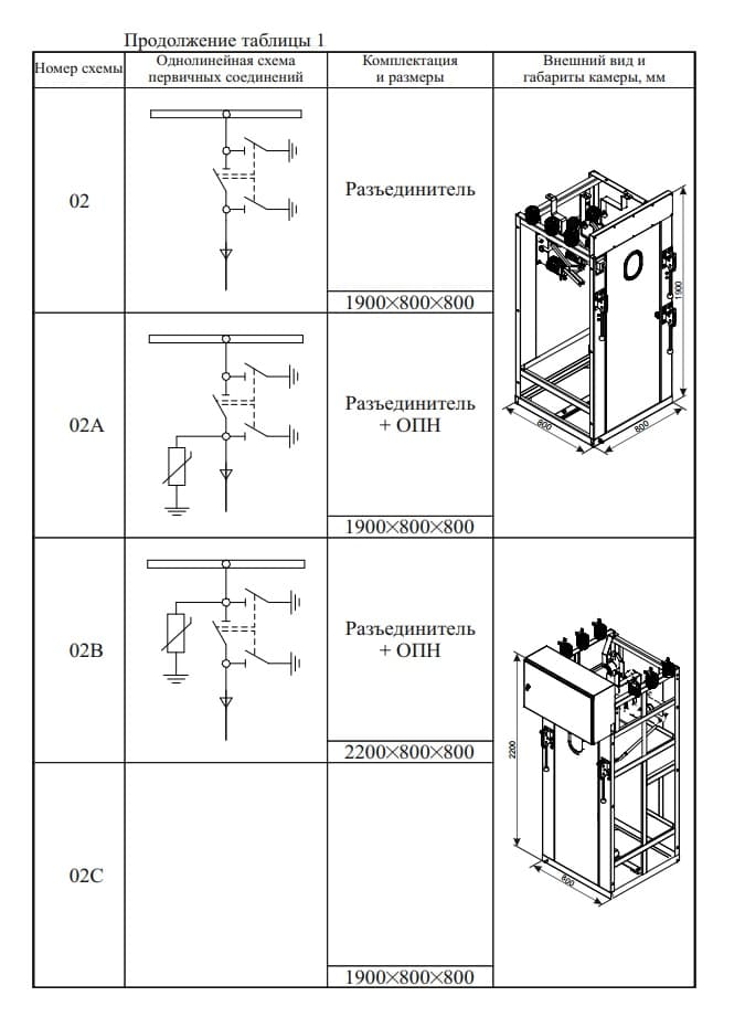
| 02 · 02A · 02V · 02S | The same with a different disconnector arrangement; variants add a surge arrester | 1900 × 800 × 800; 02V — 2200 × 800 × 800 |
Feeders with a switch-disconnector
| Scheme | What it does in the circuit | Dimensions |
|---|---|---|
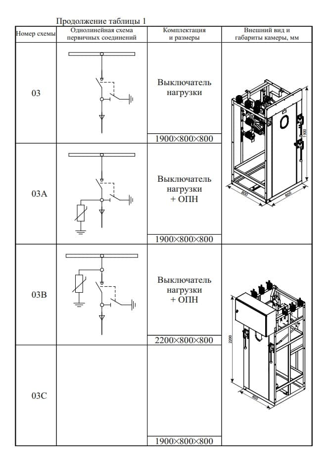
| 03 · 03A · 03V · 03S | Feeder with a switch-disconnector — makes and breaks the connection on load; plus a surge arrester | 1900 × 800 × 800; 03V — 2200 × 800 × 800 |
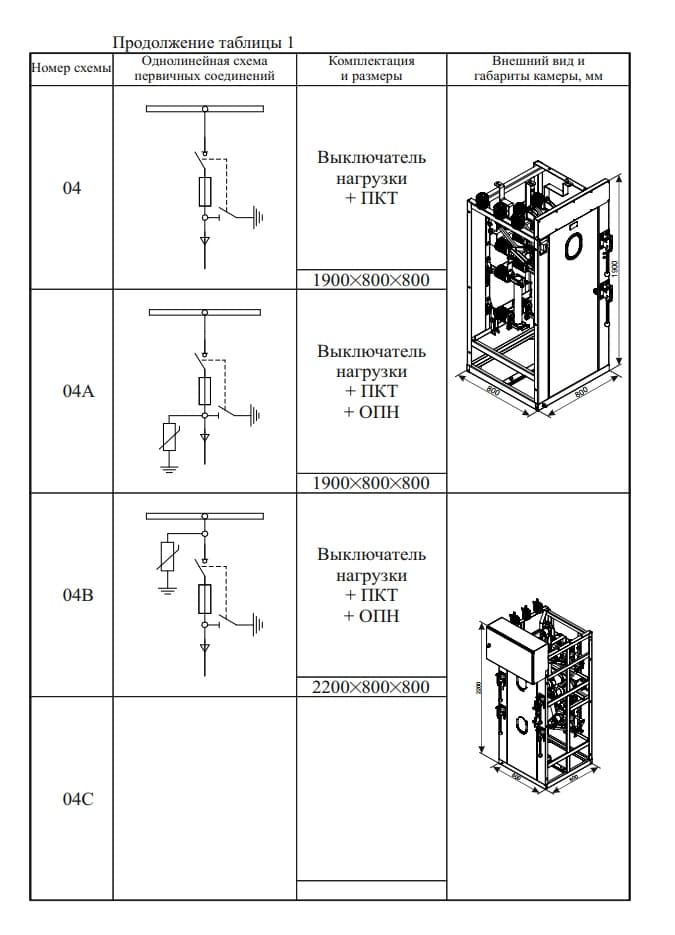
| 04 · 04A · 04V · 04S | Feeder with a switch-disconnector and PKT fuses — the connection is protected by fuse links; plus a surge arrester | 1900 × 800 × 800; 04V — 2200 × 800 × 800 |
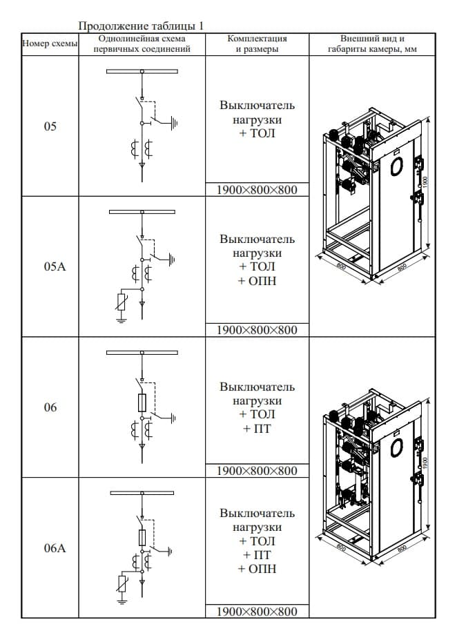
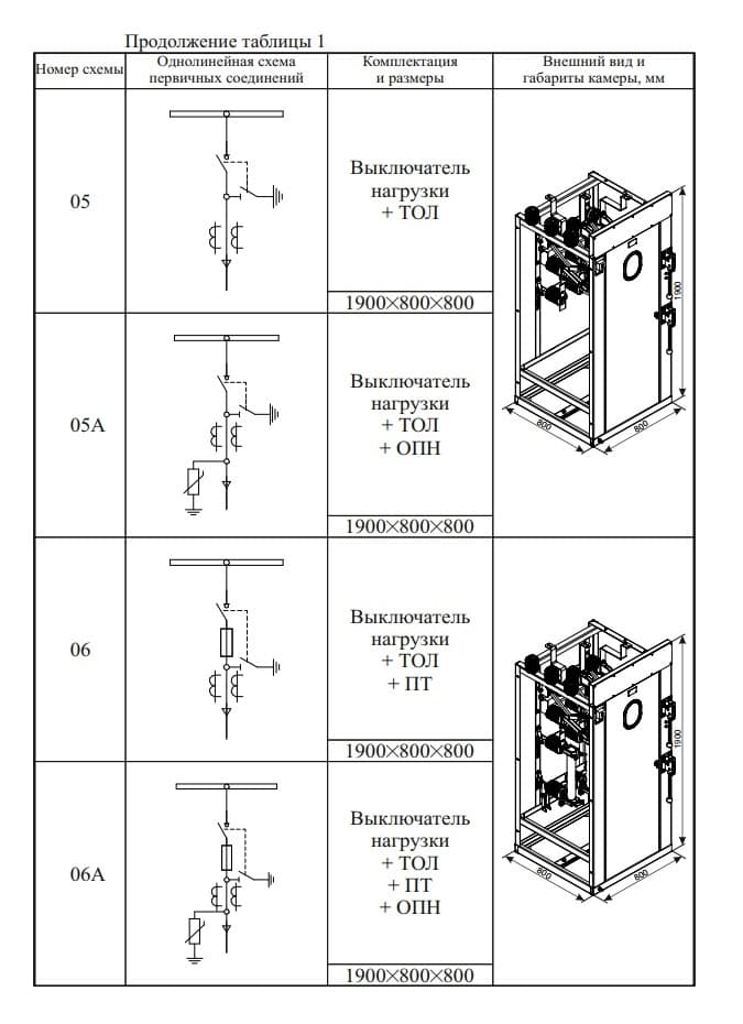
| 05 · 05A | As above with a TOL current transformer — for metering or to supply protection; plus a surge arrester | 1900 × 800 × 800 |
| 06 · 06A | Switch-disconnector, TOL current transformer and PT; plus a surge arrester | 1900 × 800 × 800 |
Metering cubicles and cubicles with voltage transformers
| Scheme | What it does in the circuit | Dimensions |
|---|---|---|
| 07 · 07A | Measurement: a disconnector with OLSP (or 3 × ZNOLP, or 2 × NOLP) | 1900 × 800 × 800 |
| 08 | Switch-disconnector with 3 × ZNOLP (or 2 × NOLP) | 1900 × 800 × 800 |
| 09 | Switch-disconnector, TOL and 3 × ZNOLP (or 2 × NOLP) | 1900 × 800 × 800 |
| 11 · 11A · 11V · 11S | Disconnector, PKN fuses and 3 × ZNOL (or NTAMI, or NAMIT); plus a surge arrester | 1900 × 800 × 800; 11V, 11S — 2200 × 800 × 800 |
| 13 · 13A · 13V · 13S | Disconnector, OLSP and 3 × ZNOLP; plus a surge arrester | 1900 × 800 × 800; 13V, 13S — 2200 × 800 × 800 |
With an auxiliary-supply transformer
| Scheme | What it does in the circuit | Dimensions |
|---|---|---|
| 12 · 12A · 12V · 12S | Auxiliary supply: PKN (PKT) fuses and an OMP transformer (or OLS, TMG, TSLU); a version with a vacuum circuit breaker and a version with an earthing switch are available | 2200 × 800 × 800 |
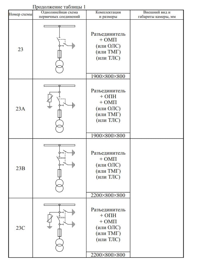
| 23 · 23A · 23V · 23S | Auxiliary supply through a disconnector and an OMP transformer (or OLS, TMG, TLS); plus a surge arrester | 1900 × 800 × 800; 23V, 23S — 2200 × 800 × 800 |
With a vacuum circuit breaker
| Scheme | What it does in the circuit | Dimensions |
|---|---|---|
| 14 · 14A · 14V · 14S | Disconnector and vacuum circuit breaker — a connection with full fault-current switching | 2200 × 800 × 800 |
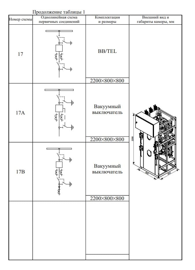
| 17 · 17A · 17V | Vacuum switching: BB/TEL in scheme 17, a vacuum circuit breaker in variants 17A and 17V | 2200 × 800 × 800 |
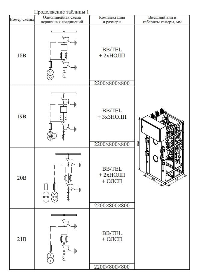
| 18V | BB/TEL and 2 × NOLP | 2200 × 800 × 800 |
| 19V | BB/TEL, 2 × NOLP and OLSP | 2200 × 800 × 800 |
| 20V | BB/TEL and OLSP | 2200 × 800 × 800 |
| 21V | BB/TEL and 3 × ZNOLP | 2200 × 800 × 800 |
Bus-section and isolating cubicles
| Scheme | What it does in the circuit | Dimensions |
|---|---|---|
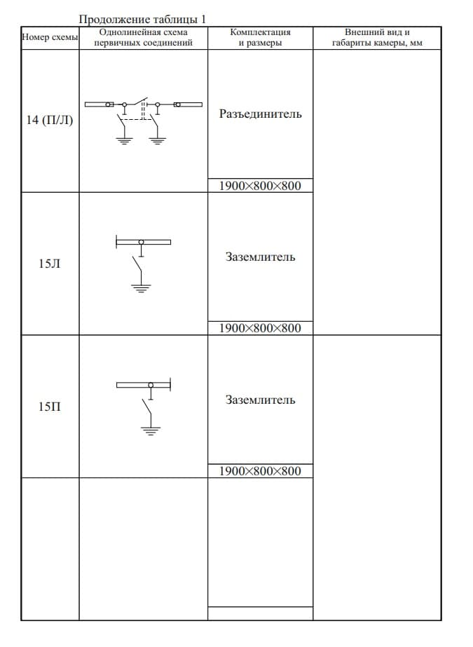
| 14 (P/L) | Disconnector, right-hand or left-hand arrangement | 1900 × 800 × 800 |
| 15L · 15P | Earthing switch, left-hand or right-hand arrangement | 1900 × 800 × 800 |
| 28 · 29 · 30 | Bus-section cubicles: disconnectors with earthing switches, three arrangements | 1900 × 800 × 800 |
Row components
| Designation | What it is | Dimensions |
|---|---|---|
| 22 · 22V | Cable-termination cubicle | 1900 × 800 × 800 and 2200 × 800 × 800 |
| ShM · ShMR | Busbar bridge: ShM-1 (ShMR-1) L = 2000 mm · ShM-2 (ShMR-2) L = 2500 mm · ShM-3 (ShMR-3) L = 3000 mm. The letter "R" means with disconnectors; L is the distance between cubicle fronts | — |
Schemes at 20 kV
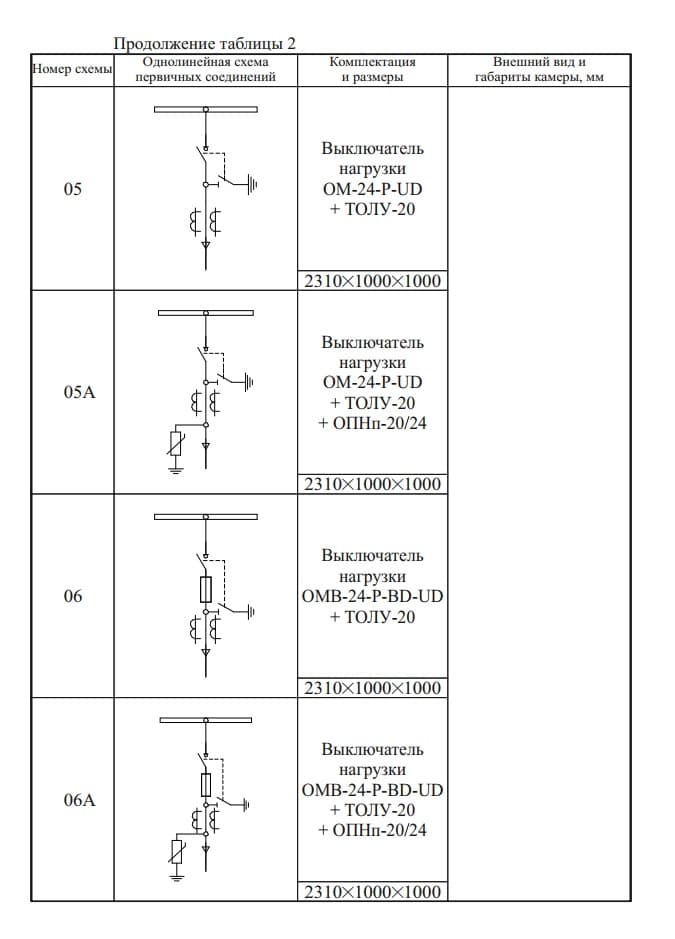
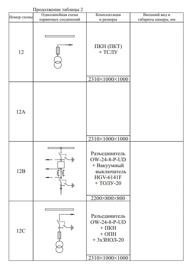
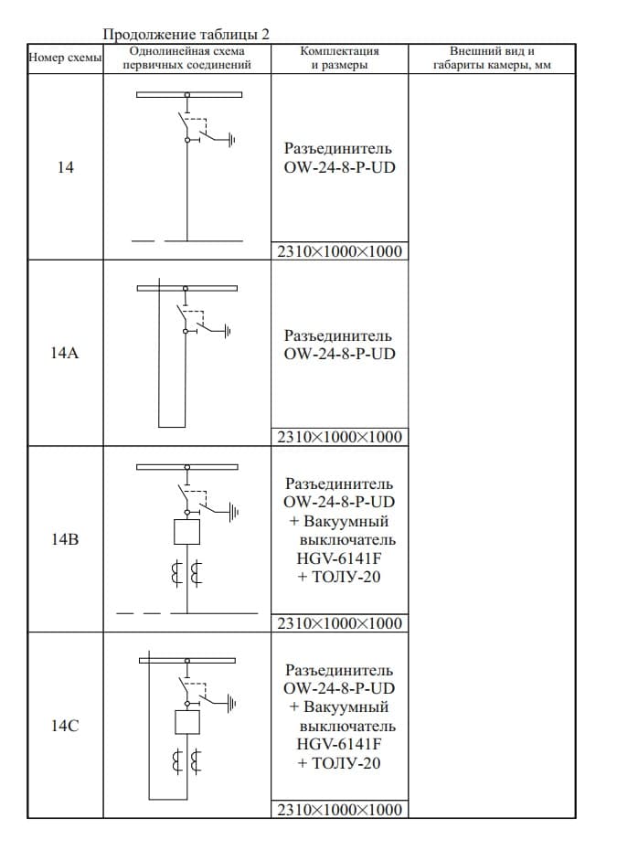
20 kV is not an exception and not a special order: it is a range of its own, with its own frame and its own apparatus. The 20 kV cubicles are built in frame 7 — 2310 × 1000 × 1000 mm. The apparatus: OW-24 disconnectors, OM-24 and OMB-24 switch-disconnectors, HGV-6141F vacuum circuit breakers, OPNp-20/24 surge arresters and TOLU-20 current transformers.
Incomers and feeders with a disconnector
| Scheme | What it does in the circuit |
|---|---|
| 01 · 01A · 01V · 01S | Incomer or feeder with an OW-24-8-P-UD disconnector; plus OPNp-20/24 |
| 02 · 02A · 02V · 02S | The same with an OW-24-8-P-UD/UG disconnector; plus OPNp-20/24 |
Feeders with a switch-disconnector
| Scheme | What it does in the circuit |
|---|---|
| 03 · 03A · 03V · 03S | Feeder with an OM-24-P-UD switch-disconnector; plus OPNp-20/24 |
| 04 · 04A · 04V · 04S | Feeder with an OMB-24-P-BD-UD switch-disconnector; plus OPNp-20/24 |
| 05 · 05A | Switch-disconnector and a TOLU-20 current transformer; plus a surge arrester |
| 06 · 06A | OM-24 or OMB-24 switch-disconnector and TOLU-20; plus a surge arrester |
With an auxiliary-supply transformer and voltage transformers
| Scheme | What it does in the circuit |
|---|---|
| 12 · 12A · 12V · 12S | Auxiliary supply: PKN (PKT) fuses and a TSLU transformer; a version with disconnector, PKN, surge arrester and 3 × ZNOL-20; a version with disconnector, HGV-6141F vacuum circuit breaker and TOLU-20 |
With a vacuum circuit breaker
| Scheme | What it does in the circuit |
|---|---|
| 14 · 14A · 14V · 14S | OW-24-8-P-UD disconnector, HGV-6141F vacuum circuit breaker and TOLU-20 |
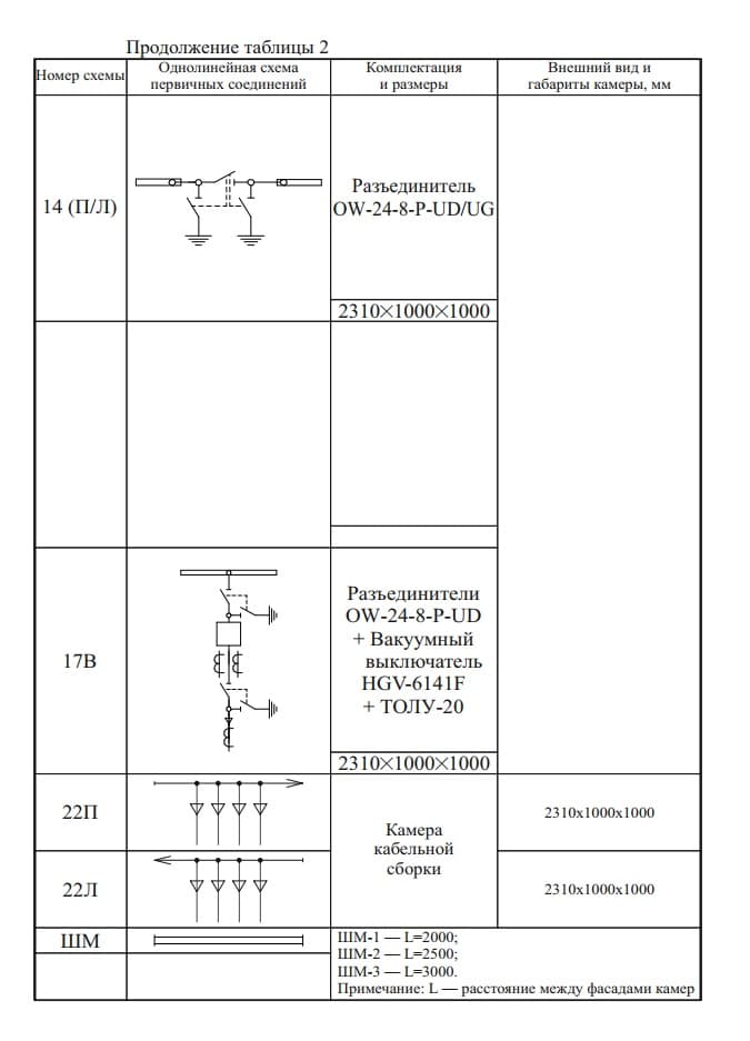
| 17V | OW-24-8-P-UD disconnectors, HGV-6141F vacuum circuit breaker and TOLU-20 |
Isolating cubicles and row components
| Designation | What it is |
|---|---|
| 14 (P/L) | OW-24-8-P-UD/UG disconnector, right-hand or left-hand arrangement |
| 22P · 22L | Cable-termination cubicle, 2310 × 1000 × 1000 mm |
| ShM | Busbar bridge: ShM-1 L = 2000 mm · ShM-2 L = 2500 mm · ShM-3 L = 3000 mm |
Frames of the 393 series
"393" is not one enclosure but a family of frames. The main-circuit scheme is selected separately from the frame.
| Frame | Dimensions W × D × H, mm |
|---|---|
| KSO-E-393 | 800 × 800 × 1900 |
| KSO-E-393V | 800 × 800 × 2200 |
| KSO-E-393VM | 800 × 800 × 2400 |
| KSO-E-393(M/V) | 650 × 800 × 2200 |
| KSO-E-393 for 20 kV (frame 7) | 1000 × 1000 × 2310 |
Any scheme in this list is built at 6, 10 or 20 kV for 630 or 1000 A. Send us a single-line diagram or a completed questionnaire and we will select the scheme, the frame and the rating for your project.
Overall dimensions
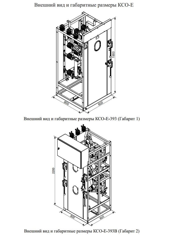
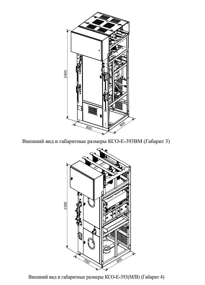
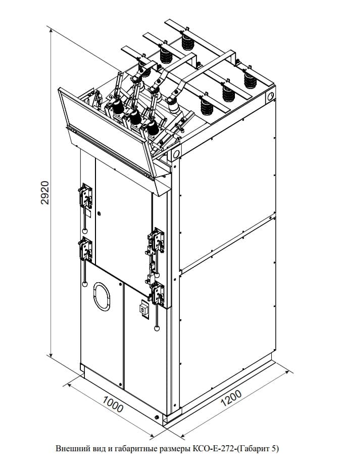
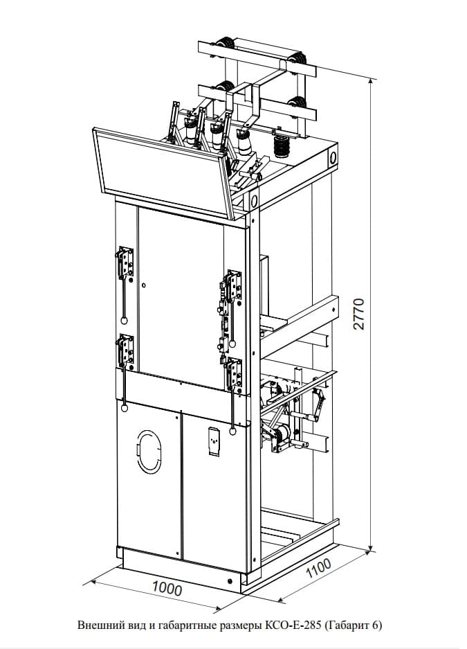
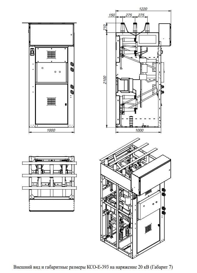
Diagram grid
Show all images (25)

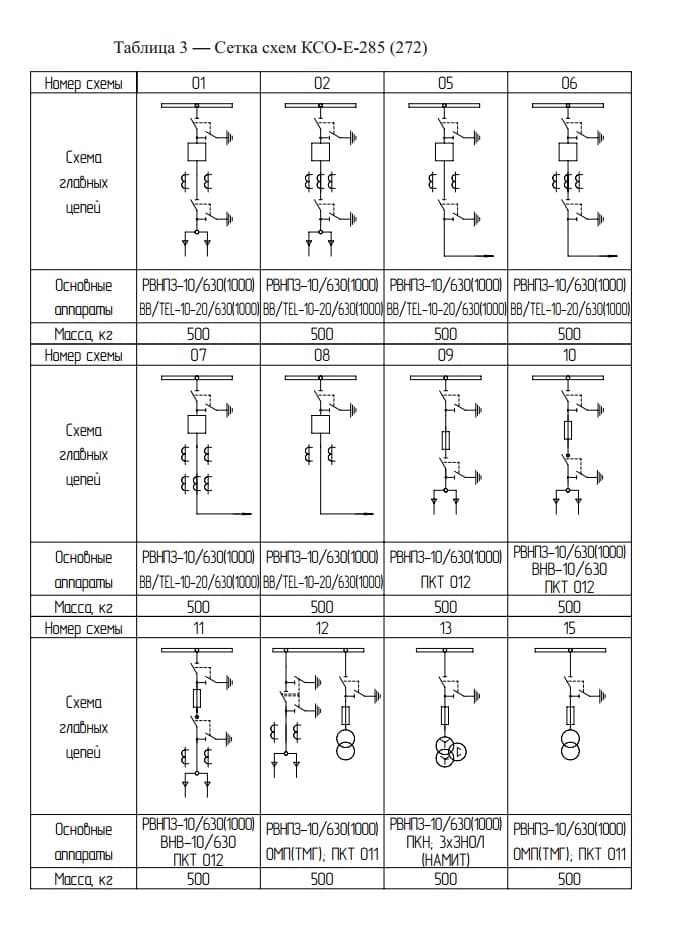
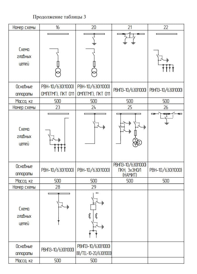
Description and Purpose
KSO-E is an assembled single-front-access switchgear cabinet for 6, 10 and 20 kV distribution switchgear (indoor installation, enclosed switchgear/enclosed transformer substations); versions for 35 kV are made to order according to technical conditions. Switching is performed by fixed vacuum circuit breakers and disconnectors; there is no SF6 (sulfur hexafluoride) gas-insulated design. Intended for distribution points at industrial facilities, transformer substations and central distribution points — receiving, metering and distribution of electricity with frequent switching operations. Suitable for designers, contractors and industrial customers. LK Energy's advantage is its own switchgear manufacturing in Odesa since 2015: cabinet ratings and single-line diagrams are made to the customer's project/technical specification, with installation and commissioning.
Find the right equipment for your site
Answer them and we will come back with a configuration and a ballpark price for your site.
FAQ
What voltage does LK Energy Group manufacture KSO-E cabinets for?
What switching devices are used in KSO-E cabinets?
Can a cabinet be ordered to a specific single-line diagram?
How does KSO differ from KRU?
How long does manufacturing take and what is the warranty?
How do I buy a KSO-E cabinet and what is needed for a quotation?
Project example
Price request:
KSO-E Type Single-Front-Access Switchgear Cabinets, Assembled (Dimension 393)
Send us your single-line diagram or specification — we will estimate the configuration, lead time and price. Preliminary estimate within 24 business hours.
+380 67 104 94 91